How To use House Electrical Plan Software

You can use many of built-in templates, electrical symbols and electical schemes examples of our House Electrical Diagram Software.
ConceptDraw is a fast way to draw: Electrical circuit diagrams, Schematics, Electrical Wiring, Circuit schematics, Digital circuits, Wiring in buildings, Electrical equipment, House electrical plans, Home cinema, Satellite television, Cable television, Closed-circuit television.
House Electrical Plan Software works across any platform, meaning you never have to worry about compatibility again. ConceptDraw PRO allows you to make electrical circuit diagrams on PC or macOS operating systems.

The vector stencils library "Electrical and telecom" contains 83 symbols of electrical and telecommunication equipment.
Use these shapes for drawing electrical and telecom system design floor plans, cabling layout schemes, and wiring diagrams in the ConceptDraw PRO diagramming and vector drawing software.
The vector stencils library "Electrical and telecom" is included in the Electric and Telecom Plans solution from the Building Plans area of ConceptDraw Solution Park.
Luminaire ceiling mount

Enclosed ceiling luminaire

Wall light

1-light bar

2-light bar

4-light bar

6-light bar

8-light bar

Down lighter

Outdoor lightning

Outdoor lightning, bollard

Batten fluorescent, 1 lamp

Batten fluorescent, 2 lamps

Batten fluorescent, 3 lamps

Batten fluorescent, 4 lamps

Surface Fluorescent Light

Modular fluorescent fitting

Modular fluorescent fitting, inverter

Modular fluorescent fitting 2

Pull-cord switch

Emergency light

Emergency light 2

Emergency sign

Switch

Switch, 1 pole

Switch, 2 pole

Switch, 2-way

Multi-switch

Switch, intermediate

Dimmer switch

Dimmer switch 2

Socket

Socket 2

Switched socket

Switched socket 2

Double socket

Double socket 2

Socket outlet

Telephone outlet

Telephone outlet 2

Stereo outlet

Television outlet

Service panel, surface

Service panel, inset

Thermostat

Ceiling fan

Hold open unit

Detector

Fire alarm

City Fire Alarm Station

Fire Alarm Station

Fire Alarm Bell

Fire Alarm Central Station

Automatic Fire Alarm Device

Main control

Ground

Doorbell

Push Button

Buzzer

Annunciator

Horn

Maid's Signal Plug

Signal Central Station

Doorbell Chime

Doorbell Transformer

Magnetic Door Hold

Intercom

Telephone Key System

Digital Satellite System

Inside Antenna

Outside Antenna

Electric Motors

Single Phase

Three of Poly Phase

Wall Mounted Electrical Junction Box for Hardware

Wall Mounted Telephone/Data Junction Box for Hardware

Card Reader Access System

Emergency Release Button

Motion Sensor

Electric Door Opener

Watchman's Station

Watchman's Central Station

Battery

The vector stencils library "Switches and relays" contains 58 symbols of electrical contacts, switches, relays, circuit breakers, selectors, connectors, disconnect devices, switching circuits, current regulators, and thermostats for electrical devices.
"In electrical engineering, a switch is an electrical component that can break an electrical circuit, interrupting the current or diverting it from one conductor to another.
The most familiar form of switch is a manually operated electromechanical device with one or more sets of electrical contacts, which are connected to external circuits. Each set of contacts can be in one of two states: either "closed" meaning the contacts are touching and electricity can flow between them, or "open", meaning the contacts are separated and the switch is nonconducting. The mechanism actuating the transition between these two states (open or closed) can be either a "toggle" (flip switch for continuous "on" or "off") or "momentary" (push-for "on" or push-for "off") type.
A switch may be directly manipulated by a human as a control signal to a system, such as a computer keyboard button, or to control power flow in a circuit, such as a light switch. Automatically operated switches can be used to control the motions of machines, for example, to indicate that a garage door has reached its full open position or that a machine tool is in a position to accept another workpiece. Switches may be operated by process variables such as pressure, temperature, flow, current, voltage, and force, acting as sensors in a process and used to automatically control a system. ... A switch that is operated by another electrical circuit is called a relay. Large switches may be remotely operated by a motor drive mechanism. Some switches are used to isolate electric power from a system, providing a visible point of isolation that can be padlocked if necessary to prevent accidental operation of a machine during maintenance, or to prevent electric shock." [Switch. Wikipedia]
"A relay is an electrically operated switch. Many relays use an electromagnet to mechanically operate a switch, but other operating principles are also used, such as solid-state relays. Relays are used where it is necessary to control a circuit by a low-power signal (with complete electrical isolation between control and controlled circuits), or where several circuits must be controlled by one signal. The first relays were used in long distance telegraph circuits as amplifiers: they repeated the signal coming in from one circuit and re-transmitted it on another circuit. Relays were used extensively in telephone exchanges and early computers to perform logical operations.
A type of relay that can handle the high power required to directly control an electric motor or other loads is called a contactor. Solid-state relays control power circuits with no moving parts, instead using a semiconductor device to perform switching. Relays with calibrated operating characteristics and sometimes multiple operating coils are used to protect electrical circuits from overload or faults; in modern electric power systems these functions are performed by digital instruments still called "protective relays"." [Relay. Wikipedia]
The shapes example "Design elements - Switches and relays" was drawn using the ConceptDraw PRO diagramming and vector drawing software extended with the Electrical Engineering solution from the Engineering area of ConceptDraw Solution Park.
Switch and relay symbols

Electrical Symbols — Transmission Paths

26 libraries of the Electrical Engineering Solution of ConceptDraw PRO make your electrical diagramming simple, efficient, and effective. You can simply and quickly drop the ready-to-use objects from libraries into your document to create the electrical diagram.
Electrical Engineering

Network Glossary Definition

Easy to draw network topology diagrams, network mapping and Cisco network topology.

Wiring Diagrams with ConceptDraw PRO

Near field communication (NFC). Computer and Network Examples
. Computer and Network Examples")
This example was created in ConceptDraw PRO using the Computer and Networks Area of ConceptDraw Solution Park and shows the Near field communication (NFC) network.
Network VOIP. Computer and Network Examples

This example was created in ConceptDraw PRO using the Computer and Networks Area of ConceptDraw Solution Park and shows the VoIP Network.
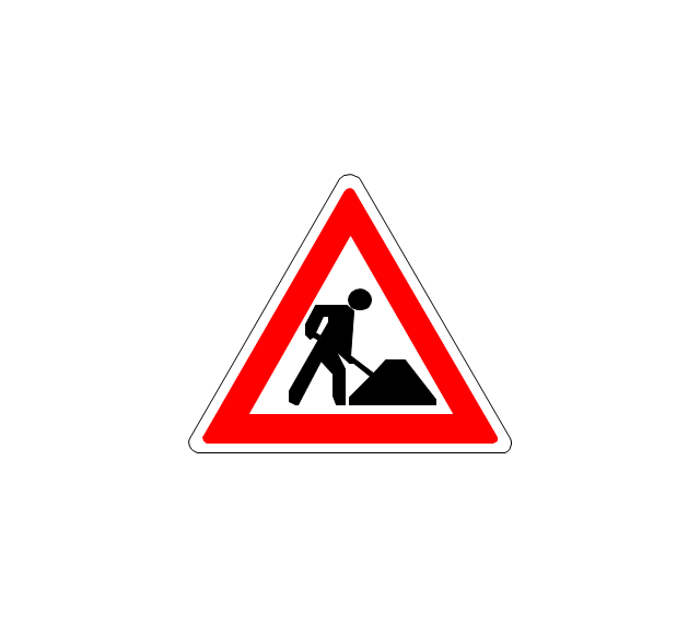
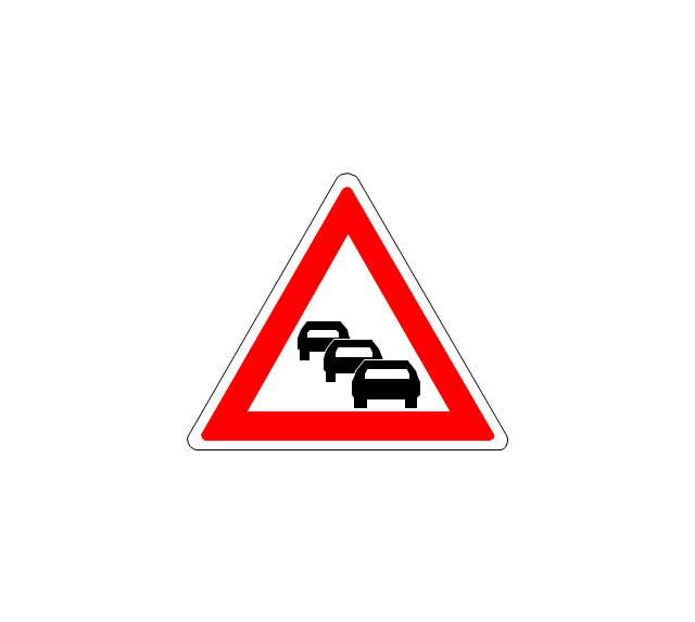
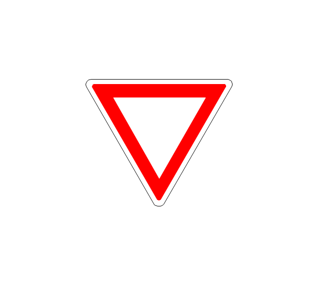
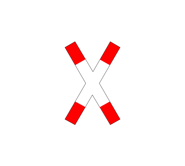
The vector stencils library "Road signs" contains 58 symbols of road signs for labeling the road and route maps, directional and transit maps, street and locator maps.
"Traffic signs or road signs are signs erected at the side of or above roads to give instructions or provide information to road users.
... many countries have adopted pictorial signs or otherwise simplified and standardized their signs to overcome language barriers, and enhance traffic safety. Such pictorial signs use symbols (often silhouettes) in place of words and are usually based on international protocols. Such signs were first developed in Europe, and have been adopted by most countries to varying degrees." [Traffic sign. Wikipedia]
The pictograms example "Road signs - Vector stencils library" was created using the ConceptDraw PRO diagramming and vector drawing software extended with the Directional Maps solution from the Maps area of ConceptDraw Solution Park.
www.conceptdraw.com/ solution-park/ maps-directional
Danger place

Intersection
Intersection 2
Bend
Double bend
Two-way traffic
Mobile bridge
Light signal
Pedestrian crossing
Road work
Back-up
Give way
Crossing
Stop

Roundabout
Pass this side
Direction to be followed

One-way street
Cycle track

No entry

No entry both directions

No power vehicles
No U-turns
No passing without stopping
No standing and parking

No parking

Speed limit
Height limit
Width limit
Weight limit
Priority over oncoming traffic
Streetcar or regular buses

Taxi status
Beginning that speed 30-Zone
End that speed 30-Zone

Pedestrian crossing 2
Police
Hotel
Breakdown service
Restaurant

P + R
Restroom
Fuel
Telephone

Recommended speed

Nodal point of a motorwa

Parking

Dead end
Motorway
End motorway
Populated zone
End populated zone
Parking with clock
Number sign (motorway)
-road-signs---vector-stencils-library.png--diagram-flowchart-example.png)
Exit
Direction to place
Board of announcement of exit
Number sign (federal highway)
-road-signs---vector-stencils-library.png--diagram-flowchart-example.png)
The vector stencils library "LDAP" contains 20 symbols of Lightweight Directory Access Protocol (LDAP) elements for drawing the LDAP Directory Services network structure diagrams.
"The Lightweight Directory Access Protocol (LDAP) is an open, vendor-neutral, industry standard application protocol for accessing and maintaining distributed directory information services over an Internet Protocol (IP) network. Directory services play an important role in developing intranet and Internet applications by allowing the sharing of information about users, systems, networks, services, and applications throughout the network. As examples, directory services may provide any organized set of records, often with a hierarchical structure, such as a corporate email directory. Similarly, a telephone directory is a list of subscribers with an address and a phone number.
LDAP is specified in a series of Internet Engineering Task Force (IETF) Standard Track publications called Request for Comments (RFCs), using the description language ASN.1. The latest specification is Version 3, published as RFC 4511. ...
A common usage of LDAP is to provide a "single sign on" where one password for a user is shared between many services, such as applying a company login code to web pages (so that staff log in only once to company computers, and then are automatically logged into the company intranet).
LDAP is based on a simpler subset of the standards contained within the X.500 standard. Because of this relationship, LDAP is sometimes called X.500-lite." [Lightweight Directory Access Protocol. Wikipedia]
The symbols example "LDAP - Vector stencils library" was created using the ConceptDraw PRO diagramming and vector drawing software extended with the Active Directory Diagrams solution from the Computer and Networks area of ConceptDraw Solution Park.
www.conceptdraw.com/ solution-park/ active-directory-diagrams
Country

Organization
Organizational unit
Generic object
Locality

Alias

Person

InetOrgPerson

Organizational person

Residential person

Organizational role

Group of names

Group of unique names

Device
cRL distribution point
dSA
dmd
Application process

Application entity

Unknown

HelpDesk
How to Create a Telecommunication Network Diagram in ConceptDraw PRO

Illustrate the Computer Network of a Building

Virtual networks. Computer and Network Examples

Well known forms of network virtualization are virtual networks based on the virtual devices (for example the network based on the virtual devices inside a hypervisor), protocol-based virtual networks (VLAN, VPN, VPLS, Virtual Wireless network, etc.) and their combinations.
This example was created in ConceptDraw PRO using the Computer and Networks Area of ConceptDraw Solution Park and shows the Virtual network.
EPN Frame-Relay and Dial-up Network. Computer and Network Examples

This example was created in ConceptDraw PRO using the Computer and Networks solution from the Computer and Networks area of ConceptDraw Solution Park. It shows the Enterprise Private Network (EPN) using the frame-relay and dial-up.
- Telephone Point Symbol
- Electrical and telecom - Vector stencils library | How To use House ...
- Process Flowchart | How To use House Electrical Plan Software ...
- Electrical Symbol For A Telephone
- Electrical Symbol Of Fan Light Point
- Symbol Of Main Control Or Intake Point
- Symbols Of Television Socket Outlet
- Telephone Socket Drawing Symbol
- Telephone Layout Symbols
- Electrical Symbol Socket Outlet
- Electronic Symbol For Wall Socket
- House Wiring Electrical Point Symbol
- Schematic Symbol Of Socket
- Electrical Outlet Symbol
- Symbol For Socket And Lamp On Wiring Plan
- Symbol Of Electrical Socket
- Symbol For Electric Socket
- Socket Outlet Symbol
- Plug Or Outlet Schematic Symbol
- Electrical Plug Symbol
- ERD | Entity Relationship Diagrams, ERD Software for Mac and Win
- Flowchart | Basic Flowchart Symbols and Meaning
- Flowchart | Flowchart Design - Symbols, Shapes, Stencils and Icons
- Flowchart | Flow Chart Symbols
- Electrical | Electrical Drawing - Wiring and Circuits Schematics
- Flowchart | Common Flowchart Symbols
- Flowchart | Common Flowchart Symbols