Electrical Symbols, Electrical Diagram Symbols

This solution provides 26 libraries which contain 926 electrical symbols from electrical engineering: Analog and Digital Logic, Composite Assemblies, Delay Elements, Electrical Circuits, Electron Tubes, IGFET, Inductors, Integrated Circuit, Lamps, Acoustics, Readouts, Logic Gate Diagram, MOSFET, Maintenance, Power Sources, Qualifying, Resistors, Rotating Equipment, Semiconductor Diodes, Semiconductors, Stations, Switches and Relays, Terminals and Connectors, Thermo, Transformers and Windings, Transistors, Transmission Paths,VHF UHF SHF.
Interior Design. Machines and Equipment — Design Elements

Process Flow Diagram Symbols

Plant Design Solutions

Restaurant Floor Plans Samples

ConceptDraw for successfully planning your restaurant floor plans. That tool can help you to plan what you will require.
The software includes sample: restaurant floor and cafe plans, restaurant floor plan layout, restaurant design, restaurant electrical plan, restaurant emergency plans, restaurant landscape design.
Electrical Symbols — IGFET

The early term metal oxide semiconductor field-effect transistor (MOSFET) is still in
use, and MOSFET is usually acceptable as a generic term for IGFETs. The metal oxide, and the insulation in the IGFET, is the insulating material between the gate terminal and the substrate between the source and drain terminals. This insulator must have very low leakage, of course, but another requirement for good performance of the transistor is that the dielectric constant of the material must be very high.
26 libraries of the Electrical Engineering Solution of ConceptDraw DIAGRAM make your electrical diagramming simple, efficient, and effective. You can simply and quickly drop the ready-to-use objects from libraries into your document to create the electrical diagram.
Interior Design. Shipping and Receiving — Design Elements

 Plant Layout Plans
Plant Layout Plans solution can be used for power plant design and plant layout design, for making the needed building plant plans and plant layouts looking professionally good. Having the newest plant layout software, the plant design solutions and in particular the ConceptDraw’s Plant Layout Plans solution, including the pre-made templates, examples of the plant layout plans, and the stencil libraries with the design elements, the architects, electricians, interior designers, builders, telecommunications managers, plant design engineers, and other technicians can use them to create the professionally looking drawings within only a few minutes.
How To Create Emergency Plans and Fire Evacuation

Electrical Schematics

Azure Services

ConceptDraw DIAGRAM extended with Azure Architecture Solution from the Computer and Networks area is a powerful diagramming and vector drawing software with extensive set of useful drawing tools for easy creating Azure Architecture Diagrams and documenting Azure services.
Telecom Wireless Plan

Interior Design. Seating Plan — Design Elements

Emergency Plan Template

 Floor Plans
Construction, repair and remodeling of the home, flat, office, or any other building or premise begins with the development of detailed building plan and floor plans. Correct and quick visualization of the building ideas is important for further construction of any building.
This cafe electrical floor plan sample shows the outlet and switch layout.
"An electrical drawing, is a type of technical drawing that shows information about power, lighting, and communication for an engineering or architectural project. Any electrical working drawing consists of "lines, symbols, dimensions, and notations to accurately convey an engineering's design to the workers, who install the electrical system on the job".
A complete set of working drawings for the average electrical system in large projects usually consists of:
(1) A plot plan showing the building's location and outside electrical wiring.
(2) Floor plans showing the location of electrical systems on every floor.
(3) Power-riser diagrams showing panel boards.
(4) Control wiring diagrams.
(5) Schedules and other information in combination with construction drawings.
Electrical drafters prepare wiring and layout diagrams used by workers who erect, install, and repair electrical equipment and wiring in communication centers, power plants, electrical distribution systems, and buildings." [Electrical drawing. Wikipedia]
The outlet and switch layout example "Cafe electrical floor plan" was created using the ConceptDraw PRO diagramming and vector drawing software extended with the Electric and Telecom Plans solution from the Building Plans area of ConceptDraw Solution Park.
Outlet and switch layout

The vector stencils library "Machines and equipment" contains 24 symbols of industrial machines and equipment.
Use the design elements library "Machines and equipment" for drawing plant interior design plans, manufacturing equipment layouts and factory floor plans using the ConceptDraw PRO diagramming and vector drawing software.
"Manufacturing is the production of goods for use or sale using labor and machines, tools, chemical and biological processing, or formulation. The term may refer to a range of human activity, from handicraft to high tech, but is most commonly applied to industrial production, in which raw materials are transformed into finished goods on a large scale.
Modern manufacturing includes all intermediate processes required for the production and integration of a product's components. Some industries, such as semiconductor and steel manufacturers use the term fabrication instead.
The manufacturing sector is closely connected with engineering and industrial design." [Manufacturing. Wikipedia]
The shapes library "Machines and equipment" is included in the Plant Layout Plans solution from the Building Plans area of ConceptDraw Solution Park.
Machines and equipment symbols

Interior Design Software. Building Plan Examples

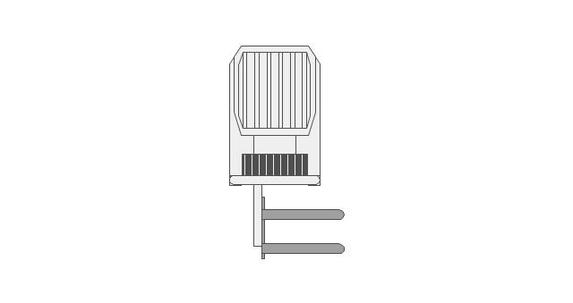
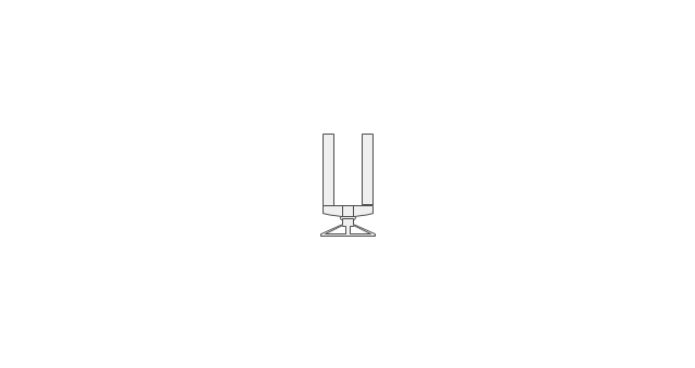
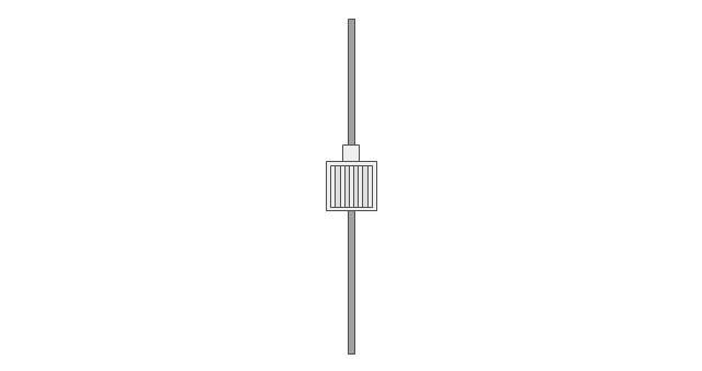
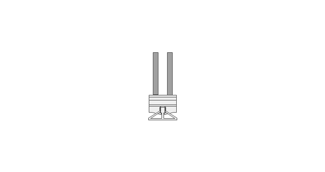
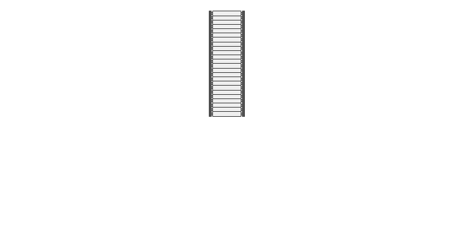
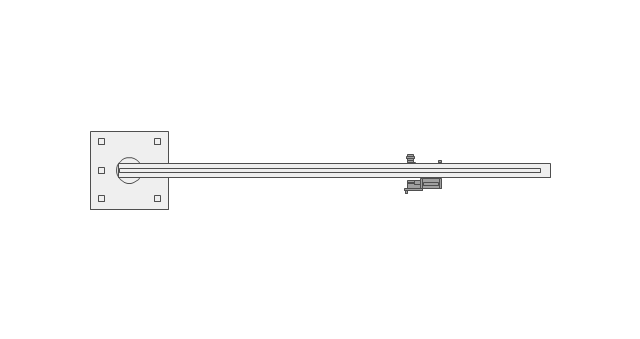
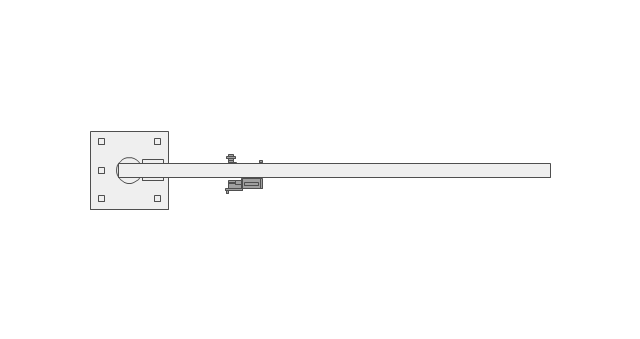
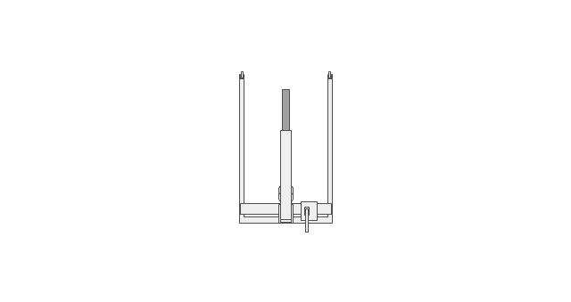
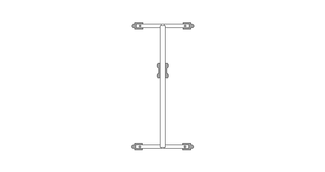
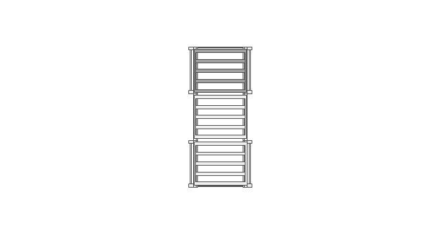
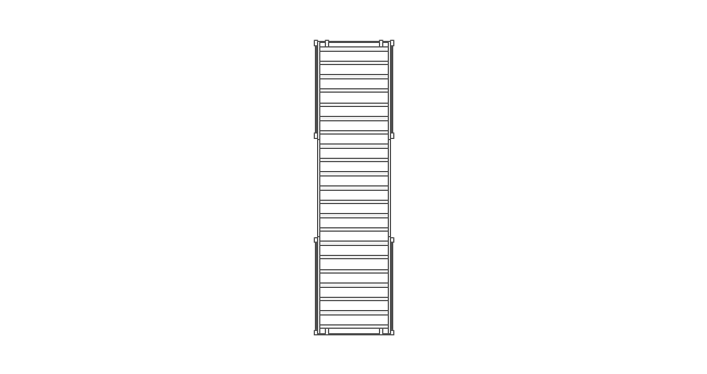
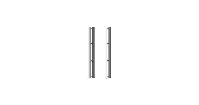
The vector stencils library "Storage and distribution" contains 24 symbols of storage and distribution equipment.
Use it for drawing plant design plans and equipment layouts in the ConceptDraw PRO diagramming and vector drawing software extended with the Plant Layout Plans solution from the Building Plans area of ConceptDraw Solution Park.
www.conceptdraw.com/ solution-park/ building-plant-layout-plans
Use it for drawing plant design plans and equipment layouts in the ConceptDraw PRO diagramming and vector drawing software extended with the Plant Layout Plans solution from the Building Plans area of ConceptDraw Solution Park.
www.conceptdraw.com/ solution-park/ building-plant-layout-plans
Diesel forklift
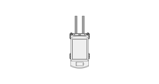
Electric forklift
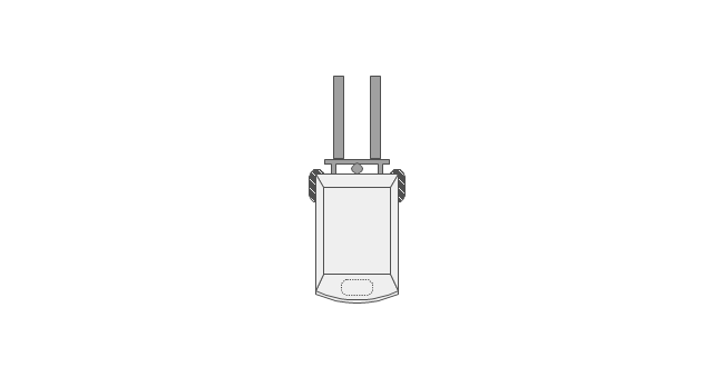
Rising cab forklift
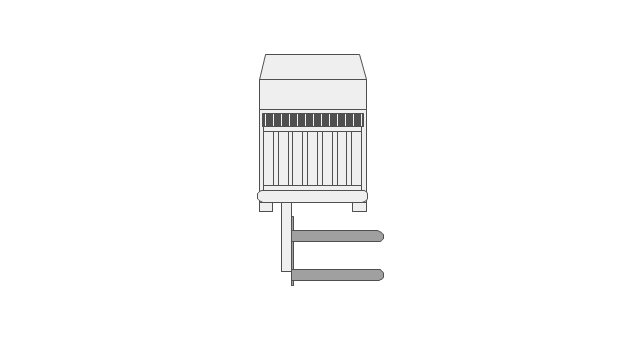
Stacking forklift
Manual pallet truck
Order picker
Powered pallet truck
Standard pallet

Conveyor belt

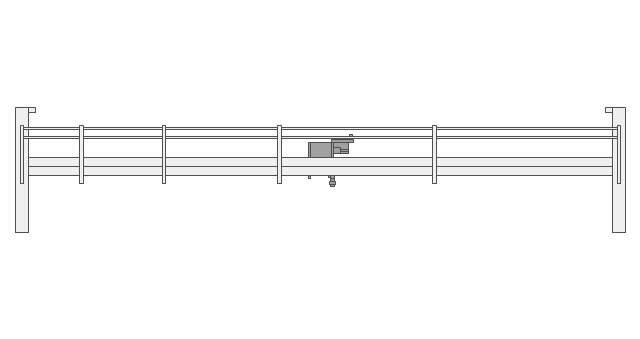
Bridge crane
Roller conveyor
Overbrace jib crane
Underbrace jib crane
Wall jib crane

Floor crane
Gantry crane
Mobile shelf
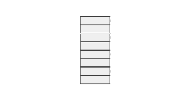
Standard shelf

Standard rack
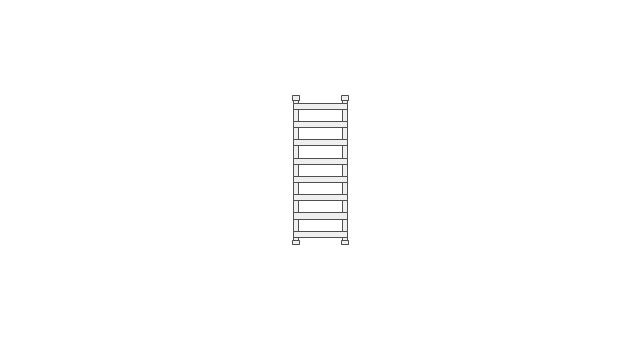
Rack section
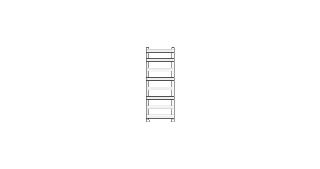
Push back rack
Sloped rack
Drive-in rack
Storage drum

The vector stencils library Initiation and annunciation contains 9 symbols of Fire Alarm Control Panel (FACP) or Fire Alarm Control Unit (FACU) elements, triggering devices, audible alarm systems, timers, security control equipment, and recording devices.
"A Fire Alarm Control Panel (FACP), or Fire Alarm Control Unit (FACU), is the controlling component of a Fire Alarm System. The panel receives information from environmental sensors designed to detect changes associated with fire, monitors their operational integrity and provides for automatic control of equipment, and transmission of information necessary to prepare the facility for fire based on a predetermined sequence. The panel may also supply electrical energy to operate any associated sensor, control, transmitter, or relay. There are four basic types of panels: coded panels, conventional panels, addressable panels, and multiplex systems." [Fire alarm control panel. Wikipedia]
Use the shapes library Initiation and annunciation to draw layout floor plans, communications schematics and wiring diagrams of security systems using the ConceptDraw PRO diagramming and vector drawing software.
The design elements library Initiation and annunciation is included in the Security and Access Plans solution from the Building Plans area of ConceptDraw Solution Park.
Initiation and annunciation symbols

- Plant Layout Plans | Draw An Electrical Factory Layout
- Electrical Symbols , Electrical Diagram Symbols | Building Drawing ...
- Electrical Symbols , Electrical Diagram Symbols | Design elements ...
- Design elements - Stations | Electrical Symbols — Stations | 2007 ...
- Process Flow Chart Examples | Electrical Symbols — Thermo ...
- How to Create a Plant Layout Design | Design elements - Machines ...
- Machine Layout Symbols
- Plant Layout Plans | Landscape Architecture with ConceptDraw ...
- Interior Design Machines and Equipment - Design Elements ...
- Design elements - Stations | Plant Layout Plans | Design elements ...
- Interior Design . Machines and Equipment — Design Elements ...
- Electrical Symbols , Electrical Diagram Symbols | Process Flow ...
- How To Draw Factory Electrical Layout
- Symbol Used For Plant Layout And Design
- Plant Layout Plans | How To use House Electrical Plan Software ...
- Electrical Symbols , Electrical Diagram Symbols | Interior Design ...
- How To use House Electrical Plan Software | Emergency Plan ...
- Factory Electrical Layout Plans
- Plant Layout Plans | How To use House Electrical Plan Software ...
- Electrical Symbols — Thermo | Electrical Symbols , Electrical ...
- ERD | Entity Relationship Diagrams, ERD Software for Mac and Win
- Flowchart | Basic Flowchart Symbols and Meaning
- Flowchart | Flowchart Design - Symbols, Shapes, Stencils and Icons
- Flowchart | Flow Chart Symbols
- Electrical | Electrical Drawing - Wiring and Circuits Schematics
- Flowchart | Common Flowchart Symbols
- Flowchart | Common Flowchart Symbols