CAD Drawing Software for Making Mechanic Diagram and Electrical Diagram Architectural Designs


Electrical Design Software

How To use House Electrical Plan Software

You can use many of built-in templates, electrical symbols and electical schemes examples of our House Electrical Diagram Software.
ConceptDraw is a fast way to draw: Electrical circuit diagrams, Schematics, Electrical Wiring, Circuit schematics, Digital circuits, Wiring in buildings, Electrical equipment, House electrical plans, Home cinema, Satellite television, Cable television, Closed-circuit television.
House Electrical Plan Software works across any platform, meaning you never have to worry about compatibility again. ConceptDraw DIAGRAM allows you to make electrical circuit diagrams on PC or macOS operating systems.
Spa Floor Plan

Electrical and Telecom Plan Software

Electrical Schematics

Electrical Schematic

Home Electrical Plan

 Electrical Engineering
This solution extends ConceptDraw DIAGRAM.9.5 (or later) with electrical engineering samples, electrical schematic symbols, electrical diagram symbols, templates and libraries of design elements, to help you design electrical schematics, digital and analog
What Is a Circle Spoke Diagram

Cisco Switches and Hubs. Cisco icons, shapes, stencils and symbols

Electrical Symbols, Electrical Schematic Symbols

Reflective Ceiling Plan

Electrical Symbols, Electrical Diagram Symbols

This solution provides 26 libraries which contain 926 electrical symbols from electrical engineering: Analog and Digital Logic, Composite Assemblies, Delay Elements, Electrical Circuits, Electron Tubes, IGFET, Inductors, Integrated Circuit, Lamps, Acoustics, Readouts, Logic Gate Diagram, MOSFET, Maintenance, Power Sources, Qualifying, Resistors, Rotating Equipment, Semiconductor Diodes, Semiconductors, Stations, Switches and Relays, Terminals and Connectors, Thermo, Transformers and Windings, Transistors, Transmission Paths,VHF UHF SHF.
ConceptDraw DIAGRAM Comparison with Omnigraffle Professional and MS Visio

Process Flow Diagram Symbols

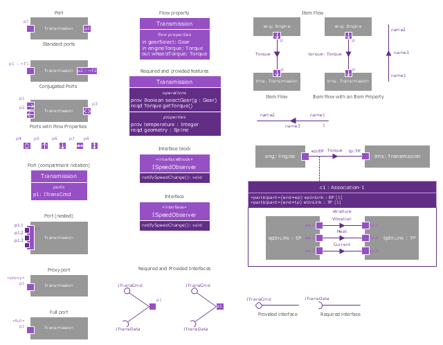
The vector stencils library "Ports and Flows" contains 26 SysML symbols.
Use it to design your SysML diagrams using ConceptDraw PRO diagramming and vector drawing software.
"The main motivation for specifying ports and flows is to enable design of modular, reusable blocks with clearly defined
ways of connecting and interacting with their context of use. This clause extends UML ports to support nested ports, and
extends blocks to support flow properties, and required and provided features, including blocks that type ports. Ports can be typed by blocks that support operations, receptions, and properties as in UML. SysML defines a specialized form of Block (InterfaceBlock) that can be used to support nested ports. SysML identifies two kinds of ports, one that exposes
features of the owning block or its internal parts (proxy ports), and another that supports its own features (full ports). Default compatibility rules are defined for connecting blocks used in composite structure, including parts and ports, with association blocks available to define more specific ways of doing this. These additional capabilities in SysML enable modelers to specify a wide variety of interconnectable components, which can be implemented through many engineering and social techniques, such as software, electrical or mechanical components, and human organizations. This clause also extends UML information flows for specifying item flows across connectors and associations." [www.omg.org/ spec/ SysML/ 1.3/ PDF]
The SysML shapes example "Design elements - Ports and Flows" is included in the SysML solution from the Software Development area of ConceptDraw Solution Park.
SysML ports and flows symbols
Fitness Plans

Office Design Software

Storage Design Software

- House Electrical Design And Drafting Pdf
- Electrical Engineering | Pdf File Of Electrical Graphics
- Hotel Electrical Design Pdf
- Cafe electrical floor plan | Design elements - Qualifying | Network ...
- Building Electrical Installation Design Pdf
- Pdf Electrical Engineering Drawing And Design 1
- Electrical Design Pdf
- Electrical Drafting And Design Pdf
- Plumbing and Piping Plans | Plumbing And Electrical Floor Plan Pdf
- Design Of Building Electrical Lighting Installation Layout Pdf
- How To use House Electrical Plan Software | Electrical Installation ...
- Electrical Layout Interior Pdf File
- Electrical Design Plan Pdf
- Electrical Graphics Pdf
- 10 Floor Office Building Network Design Pdf
- Electrical Engineering All Symbol In Pdf File
- Pdf On Electrical Layout Template For An Office Plan
- Restaurent Interior Electrical Plan Pdf
- Architectural Electrical Drawing And Symbols For House Wiring Pdf
- Electrical Design Guide For Commercial Buildings Pdf
- ERD | Entity Relationship Diagrams, ERD Software for Mac and Win
- Flowchart | Basic Flowchart Symbols and Meaning
- Flowchart | Flowchart Design - Symbols, Shapes, Stencils and Icons
- Flowchart | Flow Chart Symbols
- Electrical | Electrical Drawing - Wiring and Circuits Schematics
- Flowchart | Common Flowchart Symbols
- Flowchart | Common Flowchart Symbols