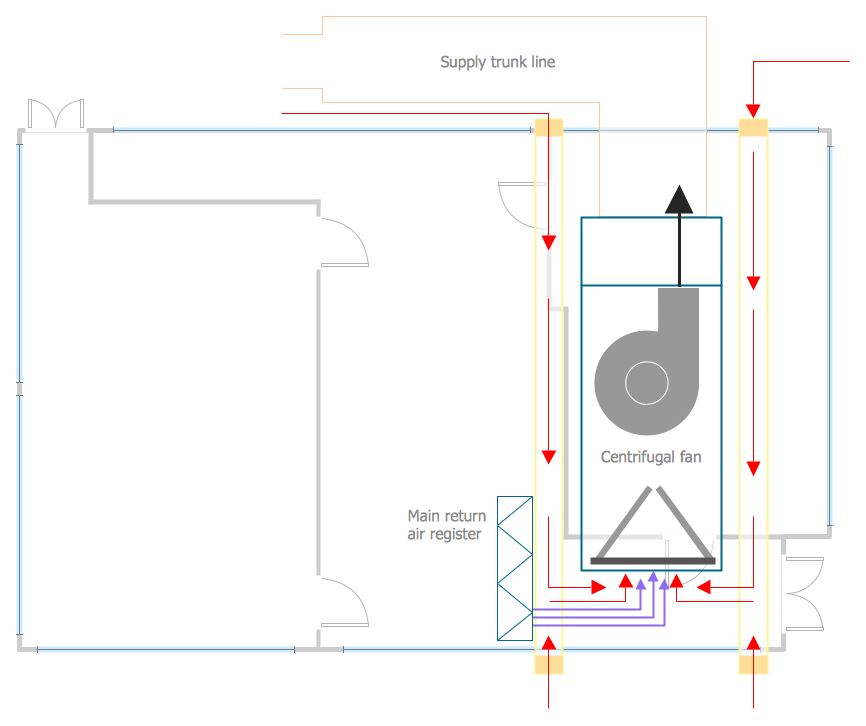
This HVAC floor plan sample shows the ventilation duct system layout.
"Ducts are used in heating, ventilation, and air conditioning (HVAC) to deliver and remove air. The needed airflows include, for example, supply air, return air, and exhaust air. Ducts commonly also deliver ventilation air as part of the supply air. As such, air ducts are one method of ensuring acceptable indoor air quality as well as thermal comfort.
A duct system is also called ductwork. Planning (laying out), sizing, optimizing, detailing, and finding the pressure losses through a duct system is called duct design." [Duct (flow). Wikipedia]
The HVAC floor plan example "Ductwork layout" was created using the ConceptDraw DIAGRAM diagramming and vector drawing software extended with the HVAC Plans solution from the Building Plans area of ConceptDraw Solution Park.
HVAC floor plan

 HVAC Plans
Use HVAC Plans solution to create professional, clear and vivid HVAC-systems design plans, which represent effectively your HVAC marketing plan ideas, develop plans for modern ventilation units, central air heaters, to display the refrigeration systems for automated buildings control, environmental control, and energy systems.
This house HVAC floor plan sample shows the ventilation system air supply diffusers and air exhaust grilles layout.
""The intentional introduction of outside air can be categorized as either mechanical ventilation, or natural ventilation. Mechanical ventilation uses fans to drive the flow of outside air into a building. This may be accomplished by pressurization (in the case of positively pressurized buildings), or by depressurization (in the case of exhaust ventilation systems). Many mechanically ventilated buildings use a combination of both, with the ventilation being integrated into the HVAC system. Natural ventilation is the intentional passive flow of outside air into a building through planned openings (such as louvers, doors, and windows). Natural ventilation does not require mechanical systems to move outside air, it relies entirely on passive physical phenomena, such as wind pressure, or the stack effect. Mixed mode ventilation systems use both mechanical and natural processes." [Ventilation (architecture). Wikipedia]
The HVAC floor plan example "House ventilation" was created using the ConceptDraw DIAGRAM diagramming and vector drawing software extended with the HVAC Plans solution from the Building Plans area of ConceptDraw Solution Park.
HVAC floor plan
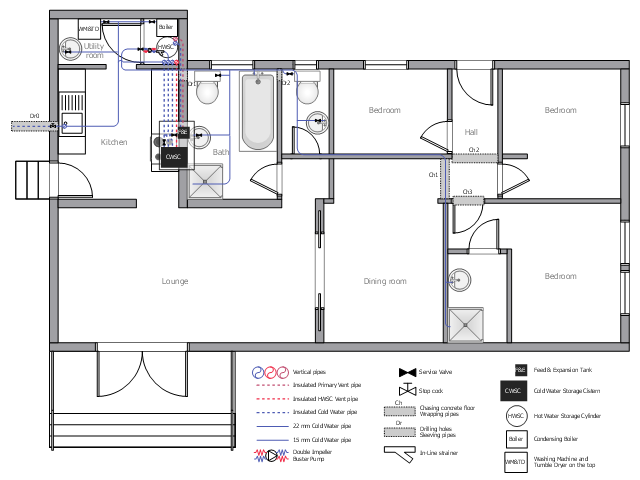
This plumbing and piping plan example depicts the house drinking water supply system.
"Drinking water, also known as potable water or improved drinking water, is water safe enough for drinking and food preparation." [Drinking water. Wikipedia]
"Modern indoor plumbing delivers clean, safe, potable water to each service point in the distribution system." [Tap water. Wikipedia]
The potable water system example "House tap water supply" was created using the ConceptDraw PRO diagramming and vector drawing software extended with the Plumbing and Piping Plans solution from the Building Plans area of ConceptDraw Solution Park.
Plumbing and piping plan
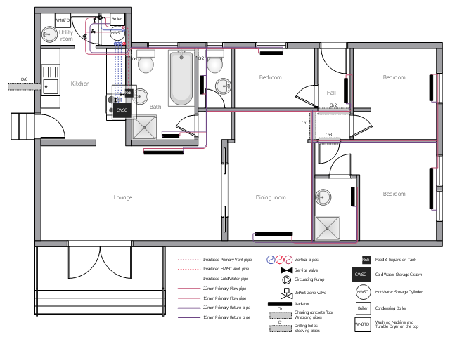
This plumbing and piping plan sample illustrates the house water heating system.
"Water heating is a thermodynamic process that uses an energy source to heat water above its initial temperature. Typical domestic uses of hot water include cooking, cleaning, bathing, and space heating. ...
Domestically, water is traditionally heated in vessels known as water heaters, kettles, cauldrons, pots, or coppers. These metal vessels that heat a batch of water do not produce a continual supply of heated water at a preset temperature. ...
Appliances that provide a continual supply of hot water are called water heaters, hot water heaters, hot water tanks, boilers, heat exchangers, geysers, or calorifiers. ... In domestic installations, potable water heated for uses other than space heating is also called domestic hot water (DHW)." [Water heating. Wikipedia]
The plumbing and piping plan example "House water heating" was created using the ConceptDraw PRO diagramming and vector drawing software extended with the Plumbing and Piping Plans solution from the Building Plans area of ConceptDraw Solution Park.
Plumbing and piping plan
Interior Design. Registers, Drills and Diffusers — Design Elements

Interior Design. Plumbing — Design Elements

HVAC Business Plan
This HVAC schematics sample depicts the house cool mode of central air pool heater. It was drawn on the base of the HVAC schematics in the post "Central Air Pool Heater" from the Nathan Stratton's blog.
"With House Cool Mode, hot gas leaves the compressor runs through the reversing value into the condenser where it condenses into a liquid. Valve #1 is ON so liquid is able to leave the outside unit and run through the filter dryer and site glass into the evaporator upstairs in the house where the liquid flashes into a gas as it passes through the expansion valve and absorbs heat from the air passing through the evaporator. The cold gas travels downstairs and outside to the compressor and the cycle starts all over again." [robotics.net/ projects/ central-air-pool-heater/ ]
The HVAC schematics example "Central air pool heater" was created using the ConceptDraw DIAGRAM diagramming and vector drawing software extended with the HVAC Plans solution from the Building Plans area of ConceptDraw Solution Park.
HVAC schematics

- Plumbing and Piping Plans | School HVAC plan | House water ...
- Ductwork layout | House tap water supply | School HVAC plan | How ...
- Duct In House Plan
- Hvac Floor Plans
- How to Create a HVAC Plan | Ventilation system layout | House ...
- How to Create a HVAC Plan | Design elements - HVAC ductwork ...
- House Plan With Toilet Duct
- HVAC Plans | How to Create a HVAC Plan | Air handler- HVAC plan ...
- Ductwork layout | Plumbing and Piping Plans | House tap water ...
- Design elements - HVAC ductwork | Plumbing and Piping Plans ...
- ERD | Entity Relationship Diagrams, ERD Software for Mac and Win
- Flowchart | Basic Flowchart Symbols and Meaning
- Flowchart | Flowchart Design - Symbols, Shapes, Stencils and Icons
- Flowchart | Flow Chart Symbols
- Electrical | Electrical Drawing - Wiring and Circuits Schematics
- Flowchart | Common Flowchart Symbols
- Flowchart | Common Flowchart Symbols