Building Drawing Software for Design School Layout
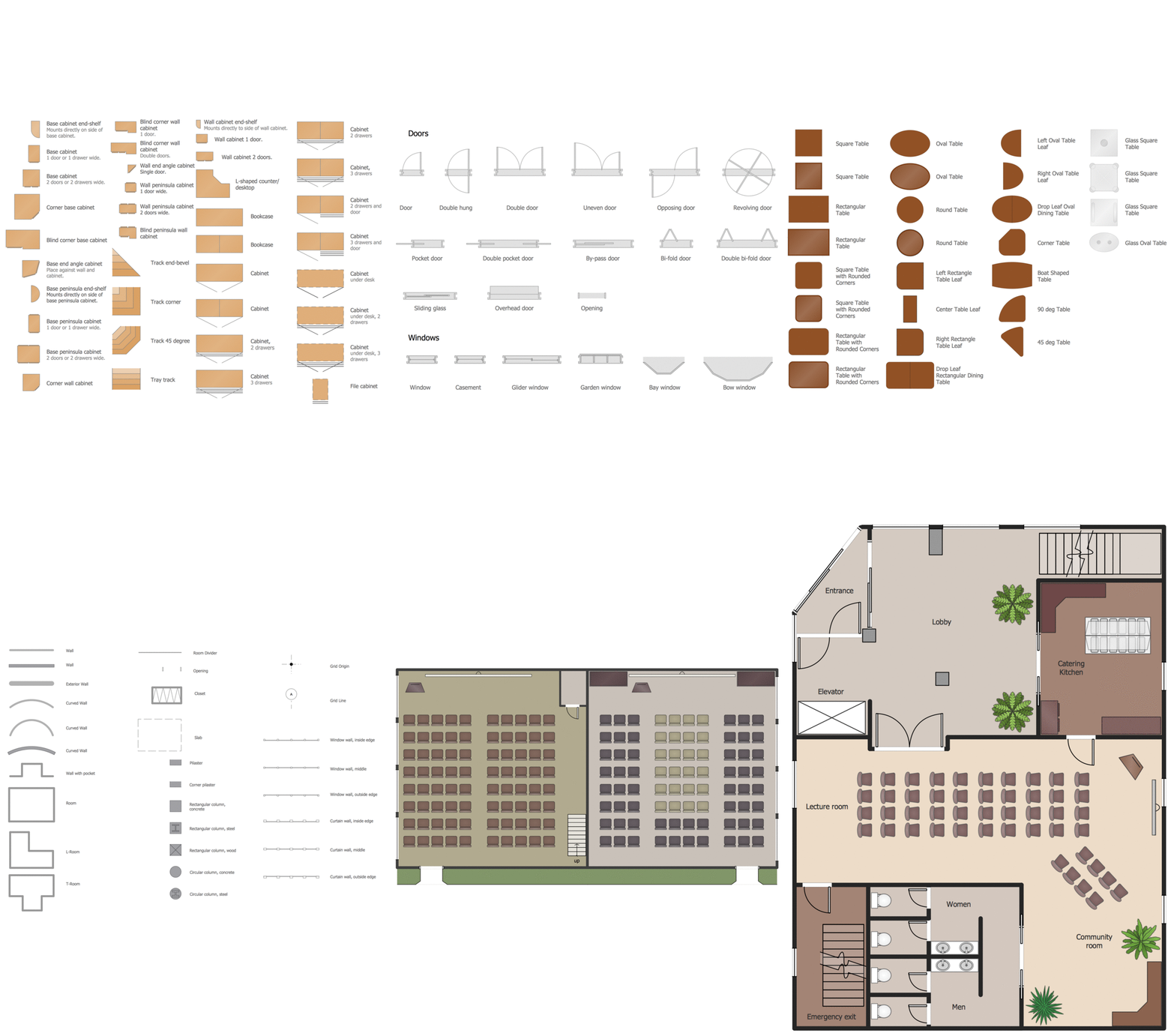
Use ConceptDraw DIAGRAM to develop the equipment the classrooms for kids in preschools, schools and colleges to the lecture halls in universities, conference rooms and even large conference halls.This software could help you to succeed at work if you did engineering job, designing or building.

Building Drawing Software for Design Office Layout Plan
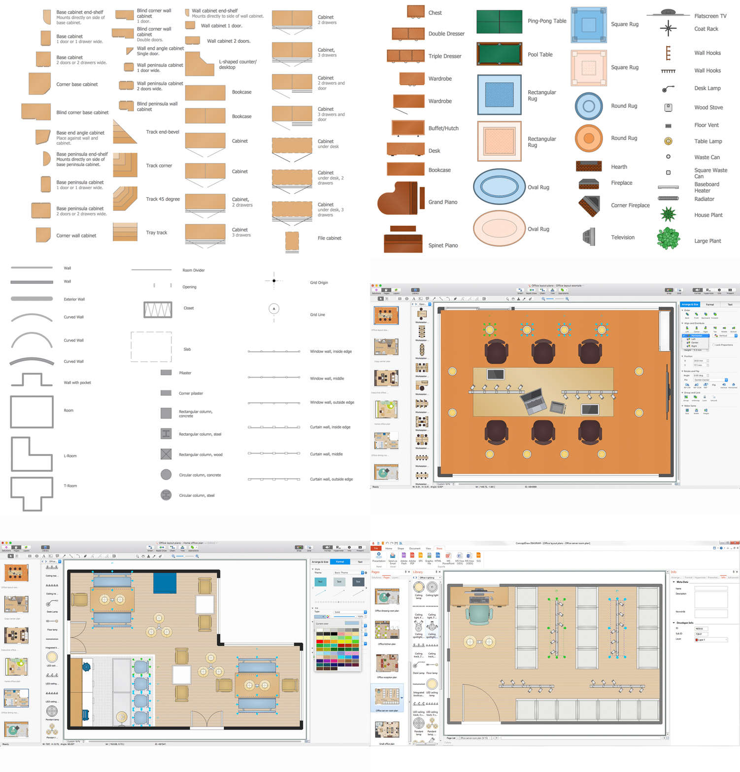
Enjoy using ConceptDraw DIAGRAM following the tutorials and make your office interior looks unique.Its Cubicles and Work Surfaces library consists of 46 objects, Office Equipment library consists of 33 objects including accessories and electronics, Office Furniture library has all 36 objects that can be found in Office Layout Plans solution any time, even right now. Check it out! Design your office and fill its space with what you want using pre-made layouts. Start now not to waste your time looking for some other software. Find 1493 vector stencils in 49 libraries in ConceptDraw DIAGRAM and use anyone you like!

How To use House Electrical Plan Software
House Electrical Plan Software for creating great-looking home floor, electrical plan using professional electrical symbols.You can use many of built-in templates, electrical symbols and electical schemes examples of our House Electrical Diagram Software.
ConceptDraw is a fast way to draw: Electrical circuit diagrams, Schematics, Electrical Wiring, Circuit schematics, Digital circuits, Wiring in buildings, Electrical equipment, House electrical plans, Home cinema, Satellite television, Cable television, Closed-circuit television.
House Electrical Plan Software works across any platform, meaning you never have to worry about compatibility again. ConceptDraw DIAGRAM allows you to make electrical circuit diagrams on PC or macOS operating systems.

Building Drawing Software for Designing Plumbing
Find our 100+ examples and 25 templates for designing diagrams as well as 1493 vector stencils from 49 libraries to start using the software for designing building drawing. You can also use the symbols from Plumbing library making your plumbing plans with help of all 21 objects necessary for such kind of schematics and you’ll find ConceptDraw DIAGRAM to be the only good enough software for your business.
Technical Drawing Software
Science and technology rapidly develop in the modern world. Electronic devices, computers and various software are very popular now. The technical drawing software is already necessity today. ConceptDraw DIAGRAM is new software for business and technical drawing. It offers a powerful tools for all kinds of technical drawing with pre-drawn shapes, free samples of business drawings and flowcharts, support for many graphic formats enables users to visually develop their technical drawings charts, schematics and diagrams in any combination of drawings, diagrams and flow charts.Local area network (LAN). Computer and Network Examples
A local area network (LAN) is a devices network that connect with each other in the scope of a home, school, laboratory, or office. Usually, a LAN comprise computers and peripheral devices linked to a local domain server. All network appliances can use a shared printers or disk storage. A local area network serve for many hundreds of users. Typically, LAN includes many wires and cables that demand a previously designed network diagram. They are used by IT professionals to visually document the LANs physical structure and arrangement.ConceptDraw - Perfect Network Diagramming Software with examples of LAN Diagrams. ConceptDraw Network Diagram is ideal for network engineers and network designers who need to draw Local Area Network diagrams.

How to Draw a Building Plans
ConceptDraw DIAGRAM is a world-class diagramming platform that lets you display, communicate, and present dynamically. It′s powerful enough to draw everything from basic flowcharts to complex engineering schematics.Building Drawing Software for Design Seating Plan
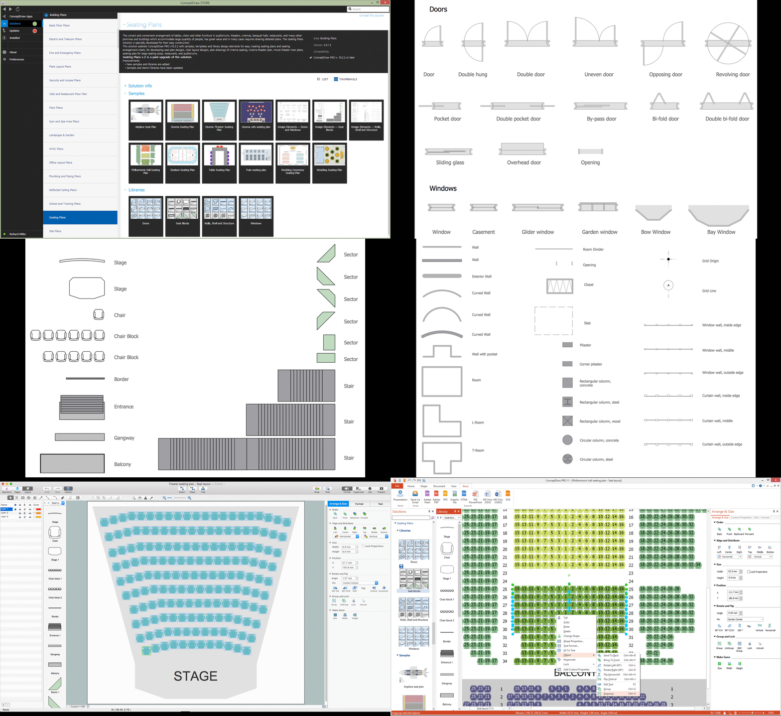
A seating plan is a scheme showing a set of seats of some place. Seats can be grouped in rows like in stadiums, or be separate. Seats can be numerated, which allows spectators to choose them beforehand, which is useful for cinemas or theatres. Customers choose places considering their proper price range and have a guaranteed seat. In addition, there is no point to arrive at the event early.
Flowchart Maker
A flowchart maker is a software showing the interaction, sequence or organization. It also known as flowchart maker or ConceptDraw DIAGRAM standard supplied with different types of symbol collections: standard symbols, branded set and authored. It used strictly for enhancing scientific or business documents with abstract explanatory pictures.Business graphic applications show a special knowledge representations and include many features for creating schematic pictures. These graphic tools are known as flowchart maker or flowchart maker software.
CAD Drawing Software for Making Mechanic Diagram and Electrical Diagram Architectural Designs
CAD (Computer-aided design) software is used for improvement the quality of design and the productivity of the designer, for creating the database for manufacturing. Computer-aided design is used in many fields: in mechanical and industrial design, in designing electronic systems and electrical diagrams for architectural design, in automotive, aerospace, shipbuilding industries.
ConceptDraw DIAGRAM : Able to Leap Tall Buildings in a Single Bound
ConceptDraw DIAGRAM is the world’s premier cross-platform business-diagramming tool. Many, who are looking for an alternative to Visio, are pleasantly surprised with how well they can integrate ConceptDraw DIAGRAM into their existing processes. With tens of thousands of template objects, and an easy method for importing vital custom objects from existing Visio documents, ConceptDraw DIAGRAM is a powerful tool for making extremely detailed diagrams, quickly and easily.Electrical Symbols, Electrical Diagram Symbols
How to create Electrical Diagram? It’s very easy! All you need is a powerful software. It wasn’t so easy to create Electrical Symbols and Electrical Diagram as it is now with electrical diagram symbols offered by the libraries of Electrical Engineering Solution from the Industrial Engineering Area at the ConceptDraw Solution Park.This solution provides 26 libraries which contain 926 electrical symbols from electrical engineering: Analog and Digital Logic, Composite Assemblies, Delay Elements, Electrical Circuits, Electron Tubes, IGFET, Inductors, Integrated Circuit, Lamps, Acoustics, Readouts, Logic Gate Diagram, MOSFET, Maintenance, Power Sources, Qualifying, Resistors, Rotating Equipment, Semiconductor Diodes, Semiconductors, Stations, Switches and Relays, Terminals and Connectors, Thermo, Transformers and Windings, Transistors, Transmission Paths,VHF UHF SHF.
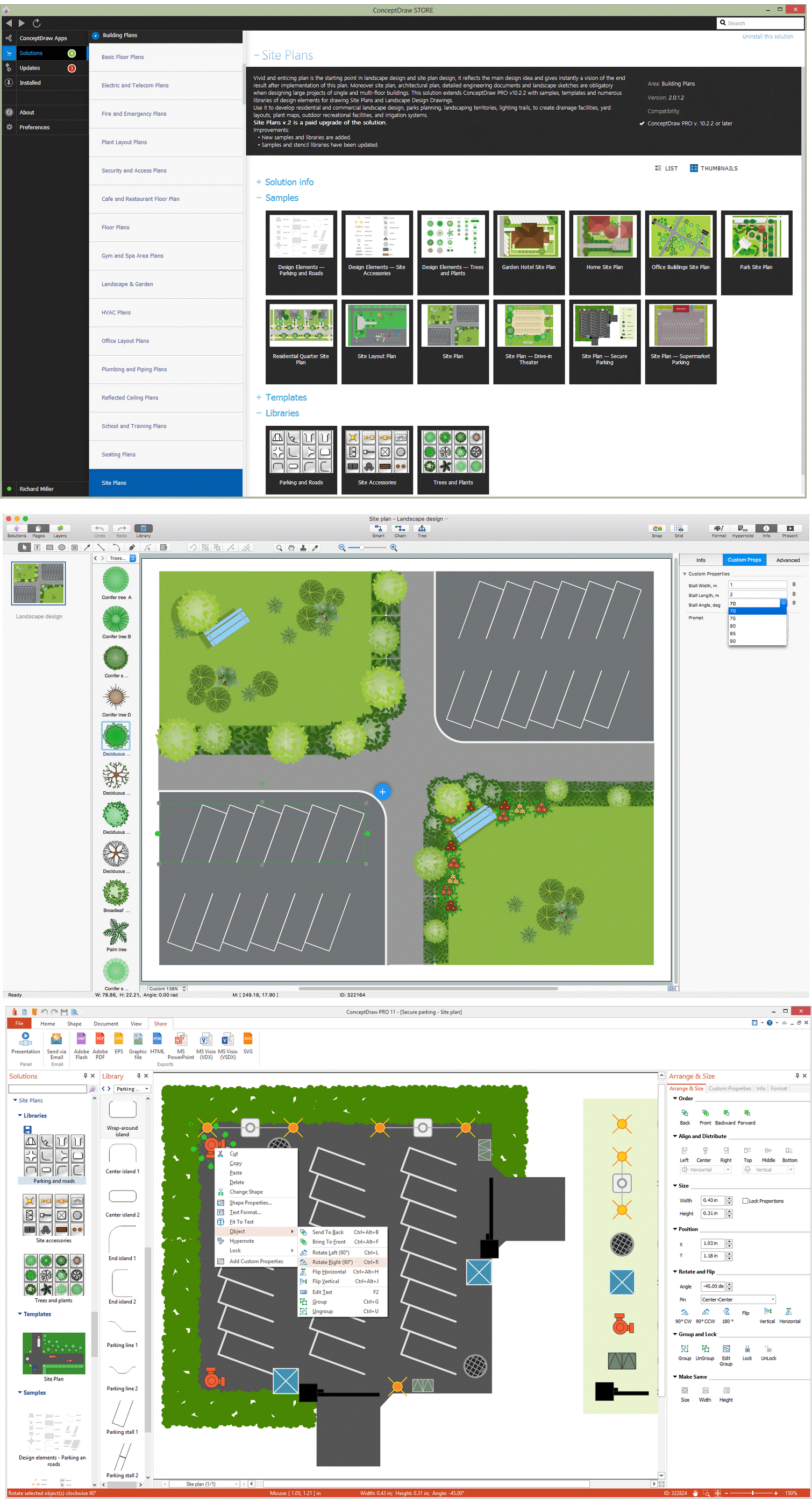
Building Drawing Software for Design Site Plan
Downloading our Building Plans solution to be able to create your own commercial landscape design as well as to make parks planning, plat maps, yard layouts, irrigation systems or outdoor recreational facilities, will contribute with your business and promote you as the one professional in your sphere.
Best Vector Drawing Application for Mac OS X
ConceptDraw DIAGRAM creates drawings, diagrams and charts with great visual appeal in Mac OS X.How To Create Restaurant Floor Plan in Minutes
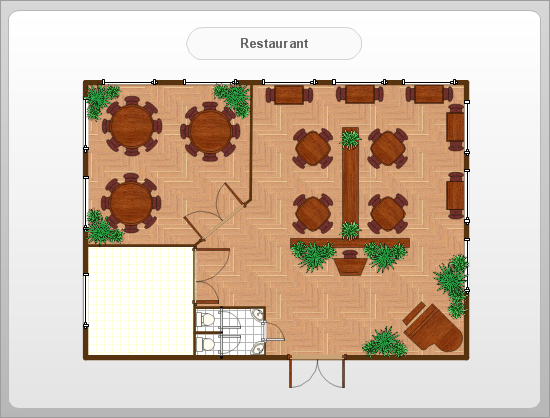
Restaurant Floor Plans solution for ConceptDraw DIAGRAM has 49 extensive restaurant symbol libraries that contains 1495 objects of building plan elements; many examples and templates for drawing floor plans and restaurant layouts.It helps make a layout for a restaurant — restaurant floor plans, cafe floor plans, bar area, floor plan of a fast food restaurant, restaurant furniture layout, etc.
ConceptDraw DIAGRAM — great restaurant floor planner. You do not need to be an artist to create great-looking restaurant floor plans in minutes.

Mechanical Drawing Symbols
Mechanical Engineering solution — 8 libraries are available with 602 commonly used mechanical drawing symbols in Mechanical Engineering Solution, including libraries called Bearings with 59 elements of roller and ball bearings, shafts, gears, hooks, springs, spindles and keys; Dimensioning and Tolerancing with 45 elements; Fluid Power Equipment containing 113 elements of motors, pumps, air compressors, meters, cylinders, actuators and gauges; Fluid Power Valves containing 93 elements of pneumatic and hydraulic valves (directional control valves, flow control valves, pressure control valves) and electrohydraulic and electropneumatic valves; as well as many other sophisticated symbols and templates for your use.Interior Design. Sport Fields — Design Elements
Making sport field and recreation area design, you might need the library called Sport fields and recreation, where you can find vector elements for making such plan, including its interior, such as pools: rectangular, kidney-shaped, oval, lap and competition ones, diving board and swing set, spa, tennis court or for playing games it can be play structure, badminton court, volleyball court, soccer and football fields, barbeque, swings and sand-box.Network Diagramming Software for Design. Cisco Network Diagrams
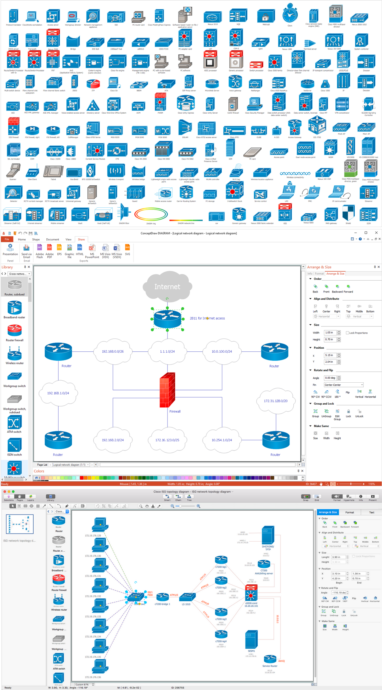
Cisco Network Diagrams use Cisco network symbols to visualize the computer networks topology and equipment connections and arrangement. They are used by IT professionals and corporate IT departments, network and system administrators to visually document the topology and design of Cisco networks. Cisco has its own brand of network diagram icons. Cisco symbols are depicting network equipment, and connections lines where their style specifies the physical connection type. A Cloud icon represents the connection between external and internal networks without determining of outside network structure. If the same LAN designed with several appliances like PCs, a server and they connected to a switch and further connected to a router, which is linked to the Internet through the WAN. Various network diagrams may be depicted, for a LAN level with personal nodes or single physical devices, hubs or servers.
HelpDesk
How to Draw a Chemical Process Flow Diagram
Process Flow Diagram widely used in modeling of processes in the chemical industry. A Chemical Process Flow diagram (PFD) is a specialized type of flowchart. With the help of Chemical Process Flow Diagram, engineers can easily specify the general scheme of the processes and chemical plant equipment. Chemical Process Flow Diagram displays the real scheme of the chemical process, the relationship between the equipment and the technical characteristics of the process. Chemical Process Flow Diagram illustrates the connections between the basic equipment as well as the overall structure of pipelines and other supporting equipment. The purpose of the PFD is to build the image of the basic idea of the chemical process. ConceptDraw DIAGRAM together with its Chemical and Process Engineering solution delivers the possibility to design Chemical Process Flow diagrams. It is designed for chemical industry engineers and designers.How to Draw a Computer Network Diagrams
Computer and Networks Drawing Solution of ConceptDraw Solution Park, which includes: Extended Cisco libraries, Wireless network, New Interactive Voice Response libraries, Rack diagram library and template objects.- Building Plan Interior Design Working Drawing Photo In Pdf
- Emergency Plan | Fire Evacuation Plan Template | Emergency Plan ...
- Telecommunication Network Diagrams | Process Flowchart | Gym ...
- How To Create Restaurant Floor Plan in Minutes | How To Draw ...
- How to Draw Chemistry Structures | Chemistry Drawings | Chemistry ...
- Drawing Cctv Layout
- Astronomy Pictures | Sun Solar System | Astronomy Symbols ...
- How to Draw Chemistry Structures | Chemistry | Design elements ...
- Building Drawing Design Element Site Plan | How To Draw Building ...
- Primary Sector Image Drawing
- Electrical Symbols, Electrical Diagram Symbols | Electrical Symbols ...
- Names And Tools Pictures Of Networking In It
- Gym Workout Plan | Hotel Floorplan | How to Draw a Building Plans ...
- Interior Design. School Layout — Design Elements | School Floor ...
- Mechanical Engineering | Mechanical Drawing Software ...
- Drawing a Nature Scene | Program to Make Flow Chart | Building ...
- How To use House Electrical Plan Software | Home Electrical Plan ...
- Technical Drawing Software | Building Drawing . Design Element ...
- Timeline Diagrams | How to Make a Timeline | Project Timeline ...
- Electrical and Telecom Plan Software | How To use House Electrical ...
- ERD | Entity Relationship Diagrams, ERD Software for Mac and Win
- Flowchart | Basic Flowchart Symbols and Meaning
- Flowchart | Flowchart Design - Symbols, Shapes, Stencils and Icons
- Flowchart | Flow Chart Symbols
- Electrical | Electrical Drawing - Wiring and Circuits Schematics
- Flowchart | Common Flowchart Symbols
- Flowchart | Common Flowchart Symbols
