State Machine Diagram


Software Defined Networking System Overview

On this example you can see the Software-Defined Networking (SDN) diagram that was created in ConceptDraw DIAGRAM using the Computer and Networks Area of ConceptDraw Solution Park.

Data Flow Diagram Model

Data Flow Diagram Examples

Agile Methodology

ConceptDraw DIAGRAM ER Diagram Tool

ConceptDraw ER Diagram Tool works across any platform, meaning you never have to worry about compatibility again. ConceptDraw DIAGRAM allows you to make Entity-Relationship Diagram (ERD) on PC or macOS operating systems.
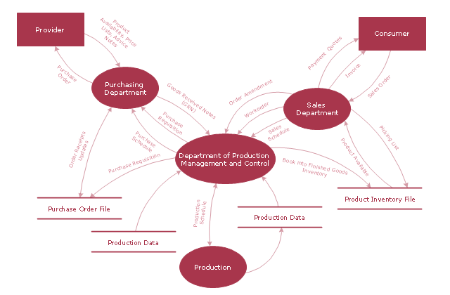
"A data flow diagram (DFD) is a graphical representation of the "flow" of data through an information system. It differs from the flowchart as it shows the data flow instead of the control flow of the program. A data flow diagram can also be used for the visualization of data processing (structured design). Data flow diagrams were invented by Larry Constantine, the original developer of structured design, based on Martin and Estrin's "data flow graph" model of computation.
It is common practice to draw a context-level Data flow diagram first which shows the interaction between the system and outside entities. The DFD is designed to show how a system is divided into smaller portions and to highlight the flow of data between those parts. This context-level Data flow diagram is then "exploded" to show more detail of the system being modeled" [Data model. Wikipedia]
The DFD (Yourdon and Coad notation) example "Model of small traditional production enterprise" was created using the ConceptDraw PRO diagramming and vector drawing software extended with the Data Flow Diagrams solution from the Software Development area of ConceptDraw Solution Park.
Data Flow Diagram Model
ConceptDraw DIAGRAM DFD Software

Process Flow Chart Symbol

The mostly used set of process flow chart symbols includes the following: Rectangle (box) process flow chart symbol, Rounded rectangle, Circle, Diamond.
UML Process Diagram Example

Booch OOD Diagram

Drawing Illustration

 Data Flow Diagrams (DFD)
Data Flow Diagrams solution extends ConceptDraw DIAGRAM software with templates, samples and libraries of vector stencils for drawing the data flow diagrams (DFD).
UML Interaction Overview Diagram. Design Elements

ConceptDraw has 393 vector stencils in the 13 libraries that helps you to start using software for designing your own UML Diagrams. You can use the appropriate stencils of UML notation from UML Interaction Overview library.
Fishbone Diagram Procedure

 Telecommunication Network Diagrams
Telecommunication Network Diagrams solution extends ConceptDraw DIAGRAM software with samples, templates, and great collection of vector stencils to help the specialists in a field of networks and telecommunications, as well as other users to create Computer systems networking and Telecommunication network diagrams for various fields, to organize the work of call centers, to design the GPRS networks and GPS navigational systems, mobile, satellite and hybrid communication networks, to construct the mobile TV networks and wireless broadband networks.
UML Activity Diagram. Design Elements

Data Flow Diagram Software

ConceptDraw DIAGRAM is a powerful Data Flow Diagram Software thanks to the Data Flow Diagrams solution from the Software Development area of ConceptDraw Solution Park.
You can use the predesigned DFD vector objects that are grouped in 3 libraries of Data Flow Diagrams solution: Data Flow Diagrams Library; Gane-Sarson Notation Library; Yourdon and Coad Notation Library.
UML Object Diagram. Design Elements

ConceptDraw has 393 vector stencils in the 13 libraries that helps you to start using software for designing your own UML Diagrams. You can use the appropriate stencils of UML notation from UML Object library.
Diagramming Software for Design UML Package Diagrams

- Draw The Traditional Control Systems Diagram
- Process Flowchart | Block Diagram | Functional Block Diagram | Use ...
- DFD - Model of small traditional production enterprise ...
- DFD - Model of small traditional production enterprise | Data flow ...
- DFD, Gane-Sarson notation - Template | DFD - Model of small ...
- HVAC control equipment - Vector stencils library | Design elements ...
- Data Flow Diagram Model | DFD - Model of small traditional ...
- DFD - Model of small traditional production enterprise | Data Flow ...
- UML Diagram of Parking | State Machine Diagram | UML ...
- UML use case diagram - Banking system | How to Create a Bank ...
- Systems development life cycle | SSADM Diagram | Process ...
- Mechanical Drawing Software | Mechanical Drawing Symbols ...
- Design elements - HVAC ductwork | HVAC control equipment ...
- Exploded Data Flow Diagram
- Chemical Engineering | Process Flow Diagram Symbols | Interior ...
- Simple Diagram Of Production System
- Design elements - Events BPMN 2.0 | Design elements - HVAC ...
- Draw Component Diagram For Library Management System And
- Design elements - Events BPMN 1.2
- Electrical Symbols — Logic Gate Diagram | Electrical Drawing ...
- ERD | Entity Relationship Diagrams, ERD Software for Mac and Win
- Flowchart | Basic Flowchart Symbols and Meaning
- Flowchart | Flowchart Design - Symbols, Shapes, Stencils and Icons
- Flowchart | Flow Chart Symbols
- Electrical | Electrical Drawing - Wiring and Circuits Schematics
- Flowchart | Common Flowchart Symbols
- Flowchart | Common Flowchart Symbols