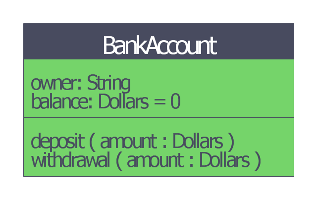
This bank account UML class diagram was redesigned from the Wikimedia Commons file: BankAccount1.svg.
[commons.wikimedia.org/ wiki/ File:BankAccount1.svg]
"Bank accounts may have a positive, or credit balance, where the bank owes money to the customer; or a negative, or debit balance, where the customer owes the bank money.
Broadly, accounts opened with the purpose of holding credit balances are referred to as deposit accounts; whilst accounts opened with the purpose of holding debit balances are referred to as loan accounts. Some accounts can switch between credit and debit balances.
Some accounts are categorized by the function rather than nature of the balance they hold, such as savings account.
All banks have their own names for the various accounts which they open for customers." [Bank account. Wikipedia]
This bank account UML class diagram example was created using the ConceptDraw PRO diagramming and vector drawing software extended with the ATM UML Diagrams solution from the Software Development area of ConceptDraw Solution Park.
Bank account UML class diagram
HelpDesk
How to Create a Bank ATM Use Case Diagram

ConceptDraw PRO diagramming software, enhanced and expanded with the ATM UML Diagrams solution, offers the full range of icons, templates and design elements needed to faithfully represent ATM and banking information system architecture using UML standards. The ATM UML Diagrams solution is useful for beginner and advanced users alike. More experienced users will appreciate a full range of vector stencil libraries and ConceptDraw PRO's powerful software, that allows you to create your ATM UML diagram in a matter of moments.
Process Flowchart


 Data Flow Diagrams (DFD)
Data Flow Diagrams solution extends ConceptDraw PRO software with templates, samples and libraries of vector stencils for drawing the data flow diagrams (DFD).
UML Diagram

Create unified modeling language (UML) diagrams with ConceptDraw.
How To Create Restaurant Floor Plan in Minutes

It helps make a layout for a restaurant — restaurant floor plans, cafe floor plans, bar area, floor plan of a fast food restaurant, restaurant furniture layout, etc.
ConceptDraw PRO — great restaurant floor planner. You do not need to be an artist to create great-looking restaurant floor plans in minutes.

 Computer Network Diagrams
Computer Network Diagrams solution extends ConceptDraw PRO software with samples, templates and libraries of vector icons and objects of computer network devices and network components to help you create professional-looking Computer Network Diagrams, to plan simple home networks and complex computer network configurations for large buildings, to represent their schemes in a comprehensible graphical view, to document computer networks configurations, to depict the interactions between network's components, the used protocols and topologies, to represent physical and logical network structures, to compare visually different topologies and to depict their combinations, to represent in details the network structure with help of schemes, to study and analyze the network configurations, to communicate effectively to engineers, stakeholders and end-users, to track network working and troubleshoot, if necessary.
ATM Solutions

UML Flowchart Symbols

The Rapid UML solution for ConceptDraw PRO software offers diversity of UML flowchart symbols for drawing all types of UML diagrams.
 Office Layout Plans
Office layouts and office plans are a special category of building plans and are often an obligatory requirement for precise and correct construction, design and exploitation office premises and business buildings. Designers and architects strive to make office plans and office floor plans simple and accurate, but at the same time unique, elegant, creative, and even extraordinary to easily increase the effectiveness of the work while attracting a large number of clients.
UML Sample Project

 Visio Exchange
Our Visio Exchange tool allows you to Import and export native MS Visio 2013 files that are in the new MS Visio drawing (VSDX) format introduced in the most recent Visio iteration. In addition, ConceptDraw PRO v10 supports the import and export of MS Visio 2007-2010 XML. (VDX) files more accurately then previous versions of ConceptDraw PRO. If you have the older MS Visio 2007-2010.
 Business Process Diagrams
Business Process Diagrams solution extends the ConceptDraw PRO BPM software with RapidDraw interface, templates, samples and numerous libraries based on the BPMN 1.2 and BPMN 2.0 standards, which give you the possibility to visualize equally easy simple and complex processes, to design business models, to quickly develop and document in details any business processes on the stages of project’s planning and implementation.
HelpDesk
How to Create a Timeline Diagram in ConceptDraw PRO

 PM Docs
PM Docs solution from ConceptDraw Solution Park extends ConceptDraw MINDMAP software with the ability to create and organize the project and company documentation, to structure information that relates to your project, to link the project documentation to tasks, phases, and resources. This solution contributes for improvement the project management abilities and enhancement the productivity of project team, makes it easier to locate the pertinent documentation over the life of a project, beginning from its planning, improves the document access and minimizes search time, lets to link or embed documentation into the project topics, helps create document, design professional Mind Maps, link the correct documents to keep them organized in a project, sort the project documents and visually differentiate the document types.
- Draw A Uml Class Dig For Opening Bank Account
- Draw A Uml Use Class Diagram For Opening A Bank Account
- Draw A Uml Diagram To Opening A Bank Account
- Draw Uml Class Diagram For Opening Bank Account
- Draw A Uml Class Diadram For Opening A Bank Account
- Draw A Uml Class Diagram For Opening Account
- UML class diagram - Bank account | UML package diagram for Bank ...
- UML class diagram - Bank account | Data Flow Diagrams (DFD ...
- Class UML Diagram for Bank Account System | Bank UML Diagram ...
- Draw A Uml Diagram For Opening A Bank Account
- UML class diagram - Bank account | How to Create a Bank ATM Use ...
- Class UML Diagram for Bank Account System | UML package ...
- Class UML Diagram for Bank Account System | UML package ...
- Draw A Uml Class Diagram For Opening Bank Account
- UML activity diagram - Cash withdrawal from ATM | UML class ...
- Drow A Uml Use Sequence Diagram For Opening A Bank Account
- Drow A Uml Use Case Diagram For Opening A Bank Account
- UML use case diagram - Banking system
- DFD - Process of account receivable | Data Flow Diagram Process ...
- Class UML Diagram for Bank Account System | UML package ...
- ERD | Entity Relationship Diagrams, ERD Software for Mac and Win
- Flowchart | Basic Flowchart Symbols and Meaning
- Flowchart | Flowchart Design - Symbols, Shapes, Stencils and Icons
- Flowchart | Flow Chart Symbols
- Electrical | Electrical Drawing - Wiring and Circuits Schematics
- Flowchart | Common Flowchart Symbols
- Flowchart | Common Flowchart Symbols