Electrical Symbols — Logic Gate Diagram

26 libraries of the Electrical Engineering Solution of ConceptDraw DIAGRAM make your electrical diagramming simple, efficient, and effective. You can simply and quickly drop the ready-to-use objects from libraries into your document to create the electrical diagram.
Electrical Symbols — Analog and Digital Logic

26 libraries of the Electrical Engineering Solution of ConceptDraw DIAGRAM make your electrical diagramming simple, efficient, and effective. You can simply and quickly drop the ready-to-use objects from libraries into your document to create the electrical diagram.
Contoh Flowchart
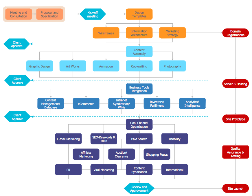
The Contoh Flowchart included to Flowcharts solution are professional looking practical samples and you can quick and easy modify them, print, or publish on web.
Electrical Symbols — Inductors

26 libraries of the Electrical Engineering Solution of ConceptDraw DIAGRAM make your electrical diagramming simple, efficient, and effective. You can simply and quickly drop the ready-to-use objects from libraries into your document to create the electrical diagram.
- Bipolar current mirror - Circuit diagram | Amplifier - Circuit diagram ...
- Electrical Drawing Software and Electrical Symbols | How To use ...
- Electrical Devices And Circuit All Symbols Image Download
- Basic Network Diagram | Simple Drawing Applications for Mac ...
- Telecommunication Network Diagrams | Design elements ...
- Electronics Circuit Diagram
- Amplifier - Circuit diagram | Composite assemblies - Vector stencils ...
- Symbol Amplifier Diagram
- Design elements - Logic gate diagram | Electrical Symbols — Logic ...
- Logic gate diagram
- Design elements - Logic gate diagram
- Design elements - Logic gate diagram | Electrical Symbols ...
- Design elements - Logic gate diagram
- Electrical Symbols, Electrical Diagram Symbols | Wiring Diagrams ...
- Electrical Symbols — Logic Gate Diagram | Design elements - Logic ...
- Circuit Symbols
- Logic gate diagram - Template | Design elements - Logic gate ...
- Design elements - Analog and digital logic | Analog and digital logic ...
- Car Electrical Wiring Diagram Software Free Download
- Amplifier - Circuit diagram
- ERD | Entity Relationship Diagrams, ERD Software for Mac and Win
- Flowchart | Basic Flowchart Symbols and Meaning
- Flowchart | Flowchart Design - Symbols, Shapes, Stencils and Icons
- Flowchart | Flow Chart Symbols
- Electrical | Electrical Drawing - Wiring and Circuits Schematics
- Flowchart | Common Flowchart Symbols
- Flowchart | Common Flowchart Symbols