The vector stencils library "Semiconductor diodes" contains 24 symbols of semiconductor diodes for drawing electronic schematics and circuit diagrams.
"In electronics, a diode is a two-terminal electronic component with asymmetric conductance; it has low (ideally zero) resistance to current in one direction, and high (ideally infinite) resistance in the other. A semiconductor diode, the most common type today, is a crystalline piece of semiconductor material with a p–n junction connected to two electrical terminals. A vacuum tube diode has two electrodes, a plate (anode) and a heated cathode. Semiconductor diodes were the first semiconductor electronic devices. ...
Today, most diodes are made of silicon, but other semiconductors such as selenium or germanium are sometimes used." [Diode. Wikipedia]
The shapes example "Design elements - Semiconductor diodes" was drawn using the ConceptDraw PRO diagramming and vector drawing software extended with the Electrical Engineering solution from the Engineering area of ConceptDraw Solution Park.
Semiconductor diode symbols

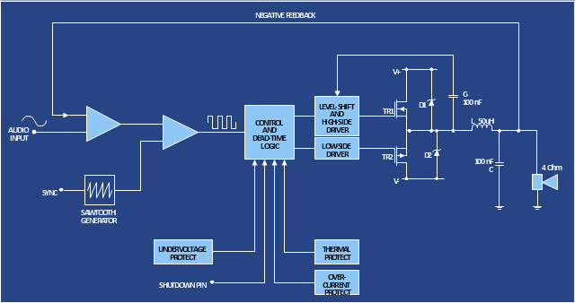
The circuit diagram example "Amplifier" was redesigned from the Wikimedia Commons file: Slika br.5.JPG.
[commons.wikimedia.org/ wiki/ File:Slika_ br.5.JPG]
This file is made available under the Creative Commons CC0 1.0 Universal Public Domain Dedication. [creativecommons.org/ publicdomain/ zero/ 1.0/ deed.en]
"An electronic amplifier, amplifier, or (informally) amp is an electronic device that increases the power of a signal. It does this by taking energy from a power supply and controlling the output to match the input signal shape but with a larger amplitude. In this sense, an amplifier modulates the output of the power supply.
There are four basic types of electronic amplifier: the voltage amplifier, the current amplifier, the transconductance amplifier, and the transresistance amplifier. A further distinction is whether the output is a linear or nonlinear representation of the input. Amplifiers can also be categorized by their physical placement in the signal chain." [Amplifier. Wikipedia]
The circuit diagram example "Amplifier" was created using the ConceptDraw PRO diagramming and vector drawing software extended with the Electrical Engineering solution from the Engineering area of ConceptDraw Solution Park.
Circuit diagram
"In electronics, a vacuum tube, electron tube (in North America), tube, or thermionic valve or valve (in British English) is a device controlling electric current through a vacuum in a sealed container. The simplest vacuum tube, the diode, contains only two elements; current can only flow in one direction through the device between the two electrodes, as electrons emitted by the hot cathode travel through the tube and are collected by the anode. Addition of a third and additional electrodes allows the current flowing between cathode and anode to be controlled in various ways. The device can be used as an electronic amplifier, a rectifier, an electronically controlled switch, an oscillator, and for other purposes.
Vacuum tubes mostly rely on thermionic emission of electrons from a hot filament or a cathode heated by the filament. Some electron tube devices rely on the properties of a discharge through an ionized gas." [Vacuum tube. Wikipedia]
"The EL34 is a thermionic valve or vacuum tube of the power pentode type. It has an international octal base (indicated by the '3' in the part number) and is found mainly in the final output stages of audio amplification circuits and was designed to be suitable as a series regulator by virtue of its high permissible voltage between heater and cathode and other parameters. The American RETMA tube designation number for this tube is 6CA7. Russian analog is 6P27S (Cyrillic: 6П27C )" [EL34. Wikipedia]
This circuit diagram sample was redrawn from the Wikipedia Commons file: EL34 schematics (circuit diagram).gif. [commons.wikimedia.org/ wiki/ File:EL34_ schematics_ %28circuit_ diagram%29.gif]
The example "Circuit diagram - EL 34 schematics" was drawn using the ConceptDraw PRO diagramming and vector drawing software extended with the Electrical Engineering solution from the Engineering area of ConceptDraw Solution Park.
EL34 shemathics

The vector stencils library "Design elements - Electron tubes" contains 36 element symbols of electron tubes.
Use it for drawing electrical schematics and electronic circuit diagrams.
"One classification of vacuum tubes is by the number of active electrodes, (neglecting the filament or heater). A device with two active elements is a diode, usually used for rectification. Devices with three elements are triodes used for amplification and switching. Additional electrodes create tetrodes, pentodes, and so forth, which have multiple additional functions made possible by the additional controllable electrodes.
Other classifications are:
(1) by frequency range (audio, radio, VHF, UHF, microwave),
(2) by power rating (small-signal, audio power, high-power radio transmitting),
(3) by design (e.g., sharp- versus remote-cutoff in some pentodes),
(4) by application (receiving tubes, transmitting tubes, amplifying or switching, rectification, mixing),
(5) special qualities (long life, very low microphonic and low noise audio amplification, and so on).
Multiple classifications may apply to a device; for example similar dual triodes can be used for audio preamplification and as flip-flops in computers, although linearity is important in the former case and long life in the latter.
Tubes have different functions, such as cathode ray tubes which create a beam of electrons for display purposes (such as the television picture tube) in addition to more specialized functions such as electron microscopy and electron beam lithography. X-ray tubes are also vacuum tubes. Phototubes and photomultipliers rely on electron flow through a vacuum, though in those cases electron emission from the cathode depends on energy from photons rather than thermionic emission." [Vacuum tube. Wikipedia]
The symbols example "Design elements - Electron tubes" was drawn using the ConceptDraw PRO diagramming and vector drawing software extended with the Electrical Engineering solution from the Engineering area of ConceptDraw Solution Park.
Vacuum tubes

The vector stencils library "Logic gate diagram" contains 17 element symbols for drawing the logic gate diagrams.
"To build a functionally complete logic system, relays, valves (vacuum tubes), or transistors can be used. The simplest family of logic gates using bipolar transistors is called resistor-transistor logic (RTL). Unlike simple diode logic gates (which do not have a gain element), RTL gates can be cascaded indefinitely to produce more complex logic functions. RTL gates were used in early integrated circuits. For higher speed and better density, the resistors used in RTL were replaced by diodes resulting in diode-transistor logic (DTL). Transistor-transistor logic (TTL) then supplanted DTL. As integrated circuits became more complex, bipolar transistors were replaced with smaller field-effect transistors (MOSFETs); see PMOS and NMOS. To reduce power consumption still further, most contemporary chip implementations of digital systems now use CMOS logic. CMOS uses complementary (both n-channel and p-channel) MOSFET devices to achieve a high speed with low power dissipation." [Logic gate. Wikipedia]
The symbols example "Design elements - Logic gate diagram" was drawn using the ConceptDraw PRO diagramming and vector drawing software extended with the Electrical Engineering solution from the Engineering area of ConceptDraw Solution Park.
Logic gate symbols

Venn Diagram Examples for Problem Solving. Venn Diagram as a Truth Table

"A logic gate is an idealized or physical device implementing a Boolean function, that is, it performs a logical operation on one or more logical inputs, and produces a single logical output. Depending on the context, the term may refer to an ideal logic gate, one that has for instance zero rise time and unlimited fan-out, or it may refer to a non-ideal physical device...
Logic gates are primarily implemented using diodes or transistors acting as electronic switches, but can also be constructed using electromagnetic relays (relay logic), fluidic logic, pneumatic logic, optics, molecules, or even mechanical elements. With amplification, logic gates can be cascaded in the same way that Boolean functions can be composed, allowing the construction of a physical model of all of Boolean logic, and therefore, all of the algorithms and mathematics that can be described with Boolean logic.
Logic circuits include such devices as multiplexers, registers, arithmetic logic units (ALUs), and computer memory, all the way up through complete microprocessors, which may contain more than 100 million gates. In practice, the gates are made from field-effect transistors (FETs), particularly MOSFETs (metal–oxide–semiconductor field-effect transistors).
Compound logic gates AND-OR-Invert (AOI) and OR-AND-Invert (OAI) are often employed in circuit design because their construction using MOSFETs is simpler and more efficient than the sum of the individual gates.
In reversible logic, Toffoli gates are used." [Logic gate. Wikipedia]
The logic gate diagram template for the ConceptDraw PRO diagramming and vector drawing software is included in the Electrical Engineering solution from the Engineering area of ConceptDraw Solution Park.
Logic gate diagram

The vector stencils library "Computer network" contains 51 symbols of computer network devices and equipment for drawing computer network diagrams.
"Network Mapping Software.
A number of software tools exist to design computer network diagrams / or generate visual maps of networks, servers, storage, services, data centers, and other peripherals. Broadly, there are two types of software tools - those that help create diagrams manually and those that generate them using automated / semi-automated approaches.
Type of Software.
(1) Manual - allows users to design and draw logical and physical topology diagrams by manually placing icons and connections.
(2) Automated - generate topology diagrams / maps by traversing the network and automatically discovering resident devices or by importing network data." [Comparison of network diagram software. Wikipedia]
ConceptDraw PRO is the software for manual design of computer network diagrams. The solutions of the Computer and Networks area in ConceptDraw Solution Park extend ConceptDraw PRO with vector stencils libraries, templates and examples for creating the computer network diagrams.
The symbols example "Computer network - Vector stencils library" was created using the ConceptDraw PRO diagramming and vector drawing software extended with the Computer and Networks solution from the Computer and Networks area of ConceptDraw Solution Park.
www.conceptdraw.com/ solution-park/ computer-and-networks
Laptop

Desktop computer

Firewall

Bus

Ethernet

Star network

FDDI Ring

Token-ring

Comm-link

Modem

Laser printer

Inkjet printer

Image scanner

City

Ethernet hub

Wireless router

Network switch

iPod Classic

iPhone/ iPod Touch

Xserve RAID

XServe

Apple Thunderbolt Display

Data store

Mac Pro

iMac

RAID

Mainframe

Rack-mountable server

Server

PDA

Cloud

Computer monitor

Workstation

Router

IP Phone

Fax

Mobile phone

Smartphone

Compact Disk

Mouse

Apple Wireless Mouse

Computer keyboard

Apple Keyboard

Radio tower

Satellite dish

Satellite

Webcam

AirPort Extreme

Airport Express

MacBook

iPhone 4

The vector stencils library "Semiconductors" contains 22 symbols of rectifiers, diodes, charge transfer and electronic conduction devices, switches, cathodes, transistors, thyristors, and transceivers for semiconductor (SIS) design.
"Semiconductor devices are electronic components that exploit the electronic properties of semiconductor materials, principally silicon, germanium, and gallium arsenide, as well as organic semiconductors. Semiconductor devices have replaced thermionic devices (vacuum tubes) in most applications. They use electronic conduction in the solid state as opposed to the gaseous state or thermionic emission in a high vacuum.
Semiconductor devices are manufactured both as single discrete devices and as integrated circuits (ICs), which consist of a number - from a few (as low as two) to billions - of devices manufactured and interconnected on a single semiconductor substrate, or wafer. ...
All transistor types can be used as the building blocks of logic gates, which are fundamental in the design of digital circuits. In digital circuits like microprocessors, transistors act as on-off switches; in the MOSFET, for instance, the voltage applied to the gate determines whether the switch is on or off.
Transistors used for analog circuits do not act as on-off switches; rather, they respond to a continuous range of inputs with a continuous range of outputs. Common analog circuits include amplifiers and oscillators.
Circuits that interface or translate between digital circuits and analog circuits are known as mixed-signal circuits.
Power semiconductor devices are discrete devices or integrated circuits intended for high current or high voltage applications. Power integrated circuits combine IC technology with power semiconductor technology, these are sometimes referred to as "smart" power devices. Several companies specialize in manufacturing power semiconductors." [Semiconductor device. Wikipedia]
The shapes example "Design elements - Semiconductors" was drawn using the ConceptDraw PRO diagramming and vector drawing software extended with the Electrical Engineering solution from the Engineering area of ConceptDraw Solution Park.
Semiconductor elements

Electrical Symbols — Logic Gate Diagram

26 libraries of the Electrical Engineering Solution of ConceptDraw DIAGRAM make your electrical diagramming simple, efficient, and effective. You can simply and quickly drop the ready-to-use objects from libraries into your document to create the electrical diagram.
- Diode Wikipedia
- Hydraulic Circuit Diagram Wikipedia
- Design elements - Semiconductor diodes | Semiconductor diodes ...
- Design elements - Semiconductor diodes | Types Of Diode And ...
- Design elements - Semiconductor diodes | Semiconductors - Vector ...
- Semiconductor diodes - Vector stencils library | Design elements ...
- Circuit diagram - EL 34 schematics | Design elements - Electron ...
- Design elements - Semiconductor diodes | Design elements - Delay ...
- Electrical Symbols — Semiconductor Diodes | Design elements ...
- Diode Vacuum Tube
- ERD | Entity Relationship Diagrams, ERD Software for Mac and Win
- Flowchart | Basic Flowchart Symbols and Meaning
- Flowchart | Flowchart Design - Symbols, Shapes, Stencils and Icons
- Flowchart | Flow Chart Symbols
- Electrical | Electrical Drawing - Wiring and Circuits Schematics
- Flowchart | Common Flowchart Symbols
- Flowchart | Common Flowchart Symbols