This finite state machine diagram example was redesigned from the Wikimedia Commons file: SdlStateMachine.png. [commons.wikimedia.org/ wiki/ File:SdlStateMachine.png]
This file is licensed under the Creative Commons Attribution-Share Alike 3.0 Unported license. [creativecommons.org/ licenses/ by-sa/ 3.0/ deed.en]
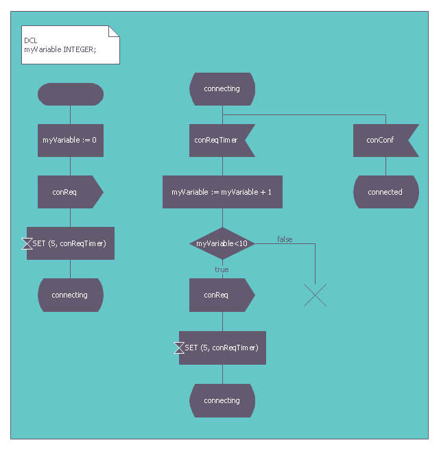
"Behavior.
Each process agent is a state machine that contributes to the action carried out by the system. A message stimulus coming from the environment or from another agent to an agent is called a signal. Signals received by a process agent are first placed in a queue (the input port). When the state machine is waiting in a state, if the first signal in the input port is enabled for that state it starts a transition leading to another state. Transitions can output signals to other agents or to the environment. A process agent is allowed to contain procedure types so that the same actions can be invoked from different places. It is also allowed to call a remote procedure type to invoke a procedure in another agent (or even another system) and wait for a response." [Specification and Description Language. Wikipedia]
The example "SDL diagram - State Machine" was created using the ConceptDraw PRO diagramming and vector drawing software extended with the Specification and Description Language (SDL) solution from the Engineering area of ConceptDraw Solution Park.
This file is licensed under the Creative Commons Attribution-Share Alike 3.0 Unported license. [creativecommons.org/ licenses/ by-sa/ 3.0/ deed.en]
"Behavior.
Each process agent is a state machine that contributes to the action carried out by the system. A message stimulus coming from the environment or from another agent to an agent is called a signal. Signals received by a process agent are first placed in a queue (the input port). When the state machine is waiting in a state, if the first signal in the input port is enabled for that state it starts a transition leading to another state. Transitions can output signals to other agents or to the environment. A process agent is allowed to contain procedure types so that the same actions can be invoked from different places. It is also allowed to call a remote procedure type to invoke a procedure in another agent (or even another system) and wait for a response." [Specification and Description Language. Wikipedia]
The example "SDL diagram - State Machine" was created using the ConceptDraw PRO diagramming and vector drawing software extended with the Specification and Description Language (SDL) solution from the Engineering area of ConceptDraw Solution Park.
Finite state machine
Used Solutions
This finite state machine diagram example was redesigned from the Wikimedia Commons file: SdlStateMachine.png. [commons.wikimedia.org/ wiki/ File:SdlStateMachine.png]
This file is licensed under the Creative Commons Attribution-Share Alike 3.0 Unported license. [creativecommons.org/ licenses/ by-sa/ 3.0/ deed.en]
"Behavior.
Each process agent is a state machine that contributes to the action carried out by the system. A message stimulus coming from the environment or from another agent to an agent is called a signal. Signals received by a process agent are first placed in a queue (the input port). When the state machine is waiting in a state, if the first signal in the input port is enabled for that state it starts a transition leading to another state. Transitions can output signals to other agents or to the environment. A process agent is allowed to contain procedure types so that the same actions can be invoked from different places. It is also allowed to call a remote procedure type to invoke a procedure in another agent (or even another system) and wait for a response." [Specification and Description Language. Wikipedia]
The example "SDL diagram - State Machine" was created using the ConceptDraw PRO diagramming and vector drawing software extended with the Specification and Description Language (SDL) solution from the Engineering area of ConceptDraw Solution Park.
Finite state machine
Used Solutions
UML Diagram for System

Local area network (LAN). Computer and Network Examples
 diagram")
ConceptDraw - Perfect Network Diagramming Software with examples of LAN Diagrams. ConceptDraw Network Diagram is ideal for network engineers and network designers who need to draw Local Area Network diagrams.

Electrical Schematics

Electrical Symbols, Electrical Diagram Symbols

This solution provides 26 libraries which contain 926 electrical symbols from electrical engineering: Analog and Digital Logic, Composite Assemblies, Delay Elements, Electrical Circuits, Electron Tubes, IGFET, Inductors, Integrated Circuit, Lamps, Acoustics, Readouts, Logic Gate Diagram, MOSFET, Maintenance, Power Sources, Qualifying, Resistors, Rotating Equipment, Semiconductor Diodes, Semiconductors, Stations, Switches and Relays, Terminals and Connectors, Thermo, Transformers and Windings, Transistors, Transmission Paths,VHF UHF SHF.
Bubble diagrams in Landscape Design with ConceptDraw DIAGRAM

ConceptDraw Arrows10 Technology

Connection points are necessary for diagramming network, flowchart and organizational charts. In ConceptDraw you connect shapes by attaching, or snapping and gluing, connectors to shape connection points.
Network Hubs

UML Diagram

Create unified modeling language (UML) diagrams with ConceptDraw.
- Different Component Used In E R Digram
- Pan Digram
- Digram Of Feul Conservation
- Hrm Functions Digram
- Table Fan Winding Digram
- ConceptDraw PRO DFD Software | Library Digram System Analysis ...
- Refinery Layout Digram
- Digram Of Man Lan Wan
- Pie Charts | Marketing Diagrams | Mass Media Digram
- Context Level Digram In Library Management System
- ERD | Entity Relationship Diagrams, ERD Software for Mac and Win
- Flowchart | Basic Flowchart Symbols and Meaning
- Flowchart | Flowchart Design - Symbols, Shapes, Stencils and Icons
- Flowchart | Flow Chart Symbols
- Electrical | Electrical Drawing - Wiring and Circuits Schematics
- Flowchart | Common Flowchart Symbols
- Flowchart | Common Flowchart Symbols