 Mechanical Engineering
This solution extends ConceptDraw PRO v.9 mechanical drawing software (or later) with samples of mechanical drawing symbols, templates and libraries of design elements, for help when drafting mechanical engineering drawings, or parts, assembly, pneumatic,
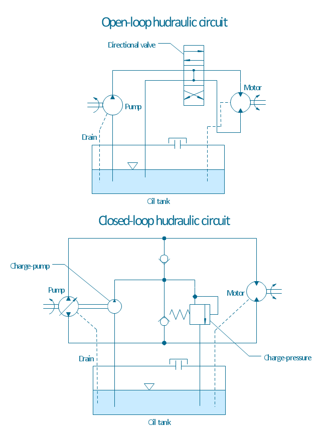
"A hydraulic circuit is a system comprising an interconnected set of discrete components that transport liquid. The purpose of this system may be to control where fluid flows (as in a network of tubes of coolant in a thermodynamic system) or to control fluid pressure (as in hydraulic amplifiers).
... hydraulic circuit theory works best when the elements (passive component such as pipes or transmission lines or active components such as power packs or pumps) are discrete and linear. This usually means that hydraulic circuit analysis works best for long, thin tubes with discrete pumps, as found in chemical process flow systems or microscale devices." [Hydraulic circuit. Wikipedia]
The engineering drawing example "Hydraulic circuits" was redrawn using ConceptDraw PRO diagramming and vector drawing software from the Wikimedia Commons file: Hydraulic circuits.png.
[commons.wikimedia.org/ wiki/ File:Hydraulic_ circuits.png]
This file is licensed under the Creative Commons Attribution-Share Alike 3.0 Unported license.
[creativecommons.org/ licenses/ by-sa/ 3.0/ deed.en]
The engineering drawing example "Hydraulic circuits" is included in the Mechanical Engineering solution from the Engineering area of ConceptDraw Solution Park.
"Directional control valves are one of the most fundamental parts in hydraulic machinery as well and pneumatic machinery. They allow fluid flow into different paths from one or more sources. They usually consist of a spool inside a cylinder which is mechanically or electrically controlled. The movement of the spool restricts or permits the flow, thus it controls the fluid flow." [Directional control valve. Wikipedia]
This example engineering drawing showing the directional control valve usage with fixed volume pump and hydraulic cylinder is redesigned using the ConceptDraw PRO diagramming and vector drawing software from Wikimedia Commons file: DCV 19.jpg.
[commons.wikimedia.org/ wiki/ File:DCV_ 19.jpg]
This file is licensed under the Creative Commons Attribution-Share Alike 3.0 Unported license.
[creativecommons.org/ licenses/ by-sa/ 3.0/ deed.en]
The fluid power equipment drawing example "Directional control valve" is included in the Mechanical Engineering solution from the Engineering area of ConceptDraw Solution Park.
- Diagram Hydraulic Pump
- Mechanical Drawing Symbols | Design elements - Hydraulic pumps ...
- Simple Hydraulic Pump Diagram
- Hydraulic 4-ported 3-position valve template - Win | Hydraulic ...
- Mechanical Drawing Symbols | Design elements - Hydraulic pumps ...
- Technical Drawing Software | Design elements - Hydraulic pumps ...
- Hydraulic Motors Engineering Drawings
- Design elements - Hydraulic pumps and motors | Hyrdaulic Pumps
- Types Hydraulic Pumps
- Design elements - Hydraulic pumps and motors | Mechanical ...
- Technical Drawing Software | Mechanical Engineering | Mechanical ...
- Design elements - Hydraulic pumps and motors | Drawing Symbol ...
- Types Of Hydraulic Pumps With Drawing
- Hydraulic circuits | Hydroullic Power Pack Diagram Wiki
- Hydraulic Pump Flowchart
- Hydraulic circuits | Mechanical Engineering | Hydraulic 4-ported 3 ...
- Hydraulic Pump Graphic Videos Download
- Pump Diagram Symbol
- Design elements - Hydraulic pumps and motors | Hydraulic pumps ...
- Technical Engineering Drawing Symbols Hydraulic
- ERD | Entity Relationship Diagrams, ERD Software for Mac and Win
- Flowchart | Basic Flowchart Symbols and Meaning
- Flowchart | Flowchart Design - Symbols, Shapes, Stencils and Icons
- Flowchart | Flow Chart Symbols
- Electrical | Electrical Drawing - Wiring and Circuits Schematics
- Flowchart | Common Flowchart Symbols
- Flowchart | Common Flowchart Symbols

