SSADM Diagram

The example below illustrates the waterfall model used in SSADM. This model involves 5 stages of developing a product such as requirements specification and its' analysis, design, coding and testing.
Structured Systems Analysis and Design Method (SSADM) with ConceptDraw DIAGRAM

Data Flow Diagram

Network Topology Graphical Examples
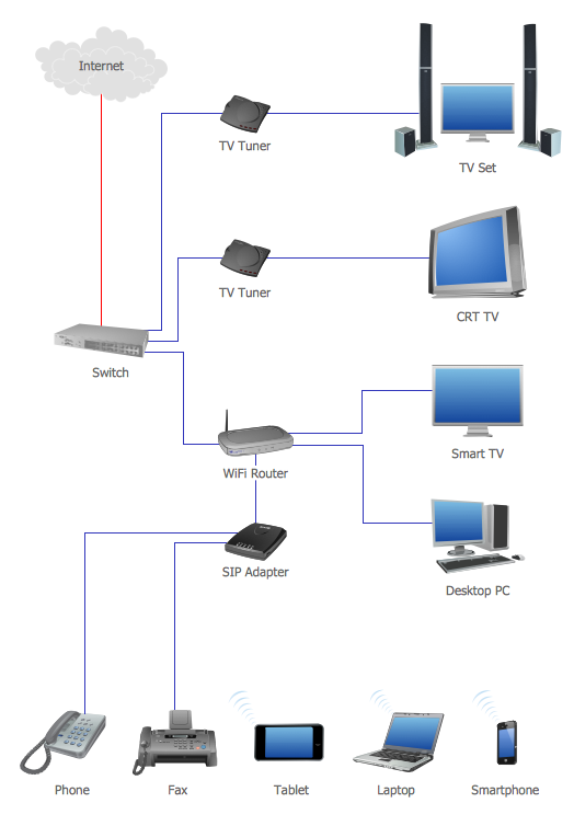
This example of computer network topology diagram shows home WLAN equipment and their connection to the Internet.
Diagramming Software for Design UML Use Case Diagrams


Basic Diagramming


ConceptDraw DIAGRAM Compatibility with MS Visio

ORM Diagram

COM and OLE Diagram

Software Diagram Examples and Templates

Software Development area of ConceptDraw Solution Park provides 5 solutions:
Data Flow Diagrams, Entity-Relationship Diagram (ERD), Graphic User Interface, IDEFO Diagrams, Rapid UML.
- Structured Systems Analysis and Design Method ( SSADM ) with ...
- SSADM Diagram | Structured Systems Analysis and Design Method ...
- Entity Life History Diagram In Ssadm
- Systems development life cycle | SSADM Diagram | Circular Flow ...
- SSADM Diagram | Data Flow Diagram Model | Data Flow Diagram ...
- Data Flow Diagrams | Structured Systems Analysis and Design ...
- Systems development life cycle | SSADM Diagram | Process ...
- SSADM Diagram | Waterfall Bar Chart | Best Program to Make ...
- Entity-relationship diagram (Crow's foot notation) | Design elements ...
- Agile Methodology | SSADM Diagram | Basic Flowchart Symbols ...
- ERD | Entity Relationship Diagrams, ERD Software for Mac and Win
- Flowchart | Basic Flowchart Symbols and Meaning
- Flowchart | Flowchart Design - Symbols, Shapes, Stencils and Icons
- Flowchart | Flow Chart Symbols
- Electrical | Electrical Drawing - Wiring and Circuits Schematics
- Flowchart | Common Flowchart Symbols
- Flowchart | Common Flowchart Symbols