HelpDesk
Downloading the Old Versions of ConceptDraw Products

The logic gate diagram example "2-bit ALU" was redesigned from the Wikimedia Commons file: 2-bit ALU.svg.
[commons.wikimedia.org/ wiki/ File:2-bit_ ALU.svg]
This file is licensed under the Creative Commons Attribution-Share Alike 3.0 Unported license. [creativecommons.org/ licenses/ by-sa/ 3.0/ deed.en]
"In digital electronics, an arithmetic and logic unit (ALU) is a digital circuit that performs integer arithmetic and logical operations. The ALU is a fundamental building block of the central processing unit of a computer, and even the simplest microprocessors contain one for purposes such as maintaining timers. The processors found inside modern CPUs and graphics processing units (GPUs) accommodate very powerful and very complex ALUs; a single component may contain a number of ALUs. ...
Most of a processor's operations are performed by one or more ALUs. An ALU loads data from input registers. Then an external control unit tells the ALU what operation to perform on that data, and then the ALU stores its result into an output register. The control unit is responsible for moving the processed data between these registers, ALU and memory." [Arithmetic logic unit. Wikipedia]
The logic gate diagram example "2-bit ALU" was created using the ConceptDraw PRO diagramming and vector drawing software extended with the Electrical Engineering solution from the Engineering area of ConceptDraw Solution Park.
Logic gate diagram

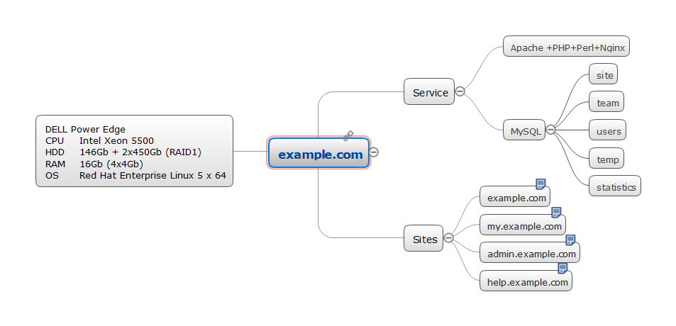
Server rack diagrams visualize the rack mounting of a computer and network equipment as a frontal view of the rack with the equipment installed. They are used when choosing which equipment or racks to buy, and to see if a particular configuration works, without having to go through a physical install.
"In the hardware sense, the word server typically designates computer models intended for hosting software applications under the heavy demand of a network environment. In this client–server configuration, one or more machines, either a computer or a computer appliance, share information with each other with one acting as a host for the other[s].
While nearly any personal computer is capable of acting as a network server, a dedicated server will contain features making it more suitable for production environments. These features may include a faster CPU, increased high-performance RAM, and increased storage capacity in the form of a larger or multiple hard drives. Servers also typically have reliability, availability and serviceability (RAS) and fault tolerance features, such as redundancy in power supplies, storage (as in RAID), and network connections." [Server (computing). Wikipedia]
This network server rack diagram example was created using the ConceptDraw PRO diagramming and vector drawing software extended with the Rack Diagrams solution from the Computer and Networks area of ConceptDraw Solution Park.
Server rack diagram

 Telecommunication Network Diagrams
Telecommunication Network Diagrams solution extends ConceptDraw DIAGRAM software with samples, templates, and great collection of vector stencils to help the specialists in a field of networks and telecommunications, as well as other users to create Computer systems networking and Telecommunication network diagrams for various fields, to organize the work of call centers, to design the GPRS networks and GPS navigational systems, mobile, satellite and hybrid communication networks, to construct the mobile TV networks and wireless broadband networks.
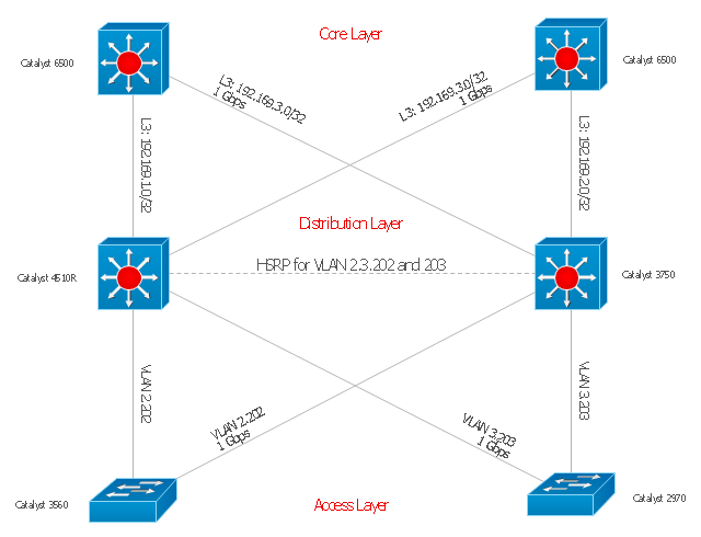
"Cisco Express Forwarding (CEF) is an advanced layer 3 switching technology used mainly in large core networks or the Internet to enhance the overall network performance. Although CEF is a Cisco proprietary protocol other vendors of multi-layer switches or high-capacity routers offer a similar functionality where layer-3 switching or routing is done in hardware (in an ASIC) instead of by software and the (central) CPU." [Cisco Express Forwarding. Wikipedia]
The computer network topology diagram example "Cisco Express Forwarding" was created using the ConceptDraw PRO diagramming and vector drawing software extended with the Cisco Network Diagrams solution from the Computer and Networks area of ConceptDraw Solution Park.
The computer network topology diagram example "Cisco Express Forwarding" was created using the ConceptDraw PRO diagramming and vector drawing software extended with the Cisco Network Diagrams solution from the Computer and Networks area of ConceptDraw Solution Park.
Network topology diagram
Servers
The vector stencils library "Hardware" contains 32 computer hardware and telecommunication equipment icons.
Use it to design your computing and telecom illustrations and infographics with ConceptDraw PRO diagramming and vector drawing software.
The vector stencils library "Hardware" is included in the Computers and Communications solution from the Illustration area of ConceptDraw Solution Park.
Use it to design your computing and telecom illustrations and infographics with ConceptDraw PRO diagramming and vector drawing software.
The vector stencils library "Hardware" is included in the Computers and Communications solution from the Illustration area of ConceptDraw Solution Park.
Rack

Workstation

Monitor with keyboard

Laptop

Laptop settings

Keyboard connection

Keyboard with mouse

Keyboard

USB computer mouse

WiFi mouse

Webcam

Remote control

Hard drive

Flash drive

Floppy

CPU
Hard drive

SD card
8GB memory card

Battery
Battery charging

Accumulator

Cable connector

Power socket

Power plug

USB cable

Electric bulb

Voltage meter

Speed control

Router

Modem

Bluetooth device

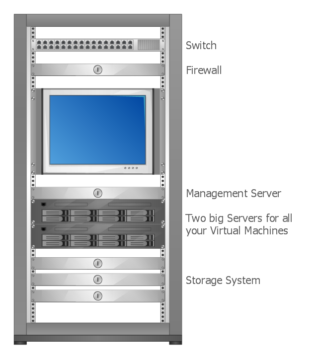
This rack diagram example was drawn on the base of picture illustrating the article "Virtualization in general, for technicans and business people" from the Banym's Blog by Dominik Zajac. [banym.de/ virtualization/ virtualization-in-general-for-technicans-and-business-people]
"Virtualization, in computing, refers to the act of creating a virtual (rather than actual) version of something, including but not limited to a virtual computer hardware platform, operating system (OS), storage device, or computer network resources." [Virtualization. Wikipedia]
"With the CPUs we have today you can virtualize up to 10 – 12 old servers to one new big machine with for example 2 x 6 core CPUs and a lot of memory. In this case you see what potential this technology has. Turn off 10 servers and run it on just one machine. That’s not the way I would do Virtualization. It’s nice to save energy but what happens if we have a problem with our one new big server? The complete organization can not work without ERP, EMail etc. and because of this we need a cluster.
Such a cluster configuration looks something like this: (rack diagram example).
Two big servers, a storage subsystem and a smaller management server. If you compare now the old configuration with the new one you can see there will be still made some points for energy efficiency. That’s not the only benefit you should have in focus, for the mature Virtualization solutions like VMware or Citrix/ XEN exist a big number of tools and documentation to make the life easier for administrators and system managers. This safes time and brings better reaction times for your IT." [banym.de/ virtualization/ virtualization-in-general-for-technicans-and-business-people]
The rack diagram example "Virtualized computer center" was created using the ConceptDraw PRO diagramming and vector drawing software extended with the Rack Diagrams solution from the Computer and Networks area of ConceptDraw Solution Park.
Rack diagram
Physical Security Plan

Data Modeling Diagram

- Cloud Computing Architecture Diagrams | Martin ERD Diagram ...
- A Well Labeled Diagram Of A Ring Topology
- Pencil Diagram Of Bus Topology
- Electrical Symbols, Electrical Diagram Symbols | Network Diagram ...
- Well Labelled Diagram Of Cloud Computing
- Server rack diagram
- Local area network (LAN). Computer and Network Examples ...
- Bank ATM use case diagram | Network Diagram Software Logical ...
- How To use House Electrical Plan Software | Electrical Symbols ...
- Cisco Express Forwarding - Network topology diagram ...
- ERD | Entity Relationship Diagrams, ERD Software for Mac and Win
- Flowchart | Basic Flowchart Symbols and Meaning
- Flowchart | Flowchart Design - Symbols, Shapes, Stencils and Icons
- Flowchart | Flow Chart Symbols
- Electrical | Electrical Drawing - Wiring and Circuits Schematics
- Flowchart | Common Flowchart Symbols
- Flowchart | Common Flowchart Symbols