UML Use Case Diagram Example. Services UML Diagram. ATM system

This sample shows the scheme of the servicing using the ATMs (Automated Teller Machines) and is used at the working of ATM banking systems, at the performing of the banking transactions.
UML Deployment Diagram
Use ConceptDraw DIAGRAM with UML deployment diagram templates, samples and stencil library from Rapid UML solution to model the physical deployment of artifacts on nodes of your software system.

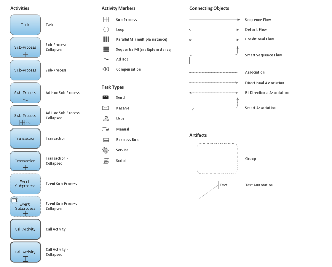
Business Process Elements: Activities

UML Deployment Diagram Example - ATM System UML diagrams

This sample shows the work of the ATM (Automated Teller Machine) banking system that is used for service and performing of the banking transactions using ATMs. System engineers can use comprehensive UML diagrams solution.
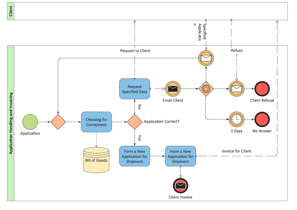
 Business Process Diagrams
Business Process Diagrams solution extends the ConceptDraw DIAGRAM BPM software with RapidDraw interface, templates, samples and numerous libraries based on the BPMN 1.2 and BPMN 2.0 standards, which give you the possibility to visualize equally easy simple and complex processes, to design business models, to quickly develop and document in details any business processes on the stages of project’s planning and implementation.
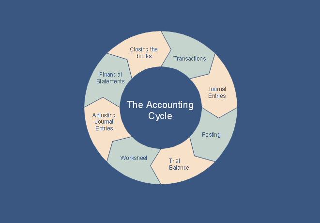
What is the Accounting Cycle?
Bank Sequence Diagram

Steps in the Accounting Process
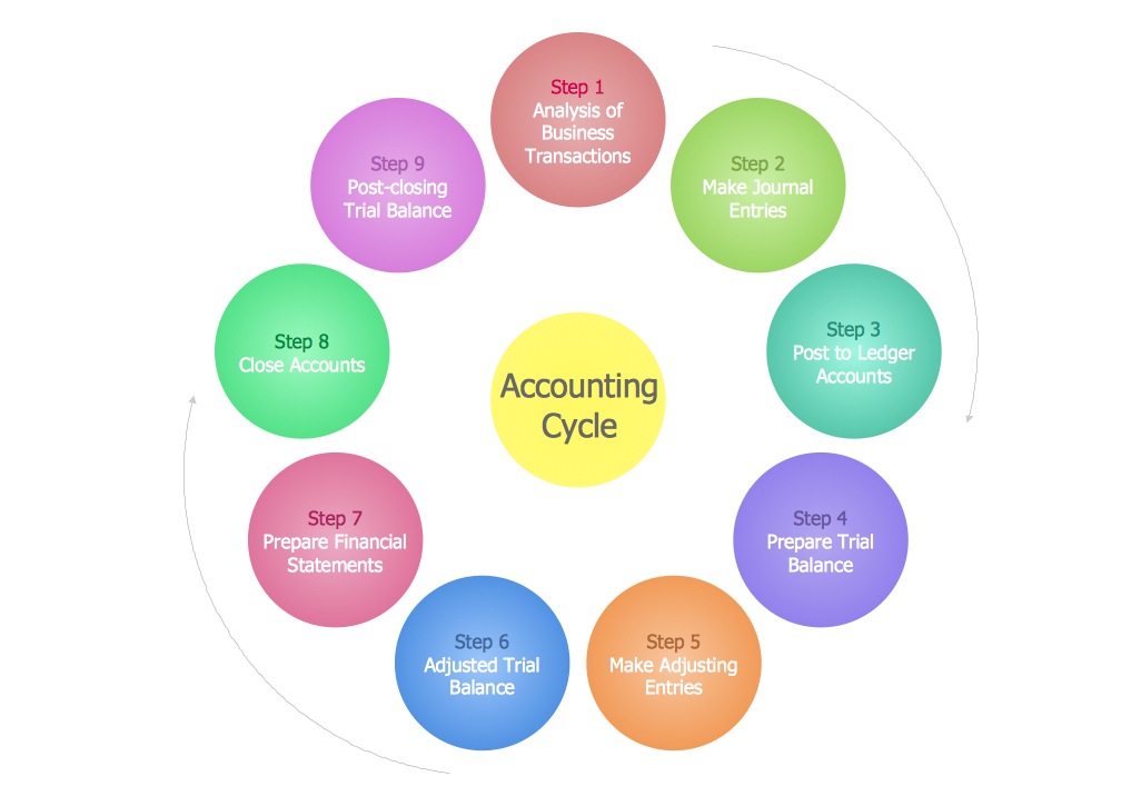
9 steps in the accounting process: Analysis of Business Transactions, Make Journal Entries, Post to Ledger Accounts, Prepare Trial Balance, Make Adjusting Entries, Adjusted Trial Balance, Prepare Financial Statements, Close Accounts, Post-Closing Trial Balance.
Financial Trade UML Use Case Diagram Example

This sample shows the work of the Financial Trade sphere and can be used by trading companies, commercial organizations, traders, different exchanges.
HelpDesk
How to Create a Bank ATM Use Case Diagram

ConceptDraw DIAGRAM diagramming software, enhanced and expanded with the ATM UML Diagrams solution, offers the full range of icons, templates and design elements needed to faithfully represent ATM and banking information system architecture using UML standards. The ATM UML Diagrams solution is useful for beginner and advanced users alike. More experienced users will appreciate a full range of vector stencil libraries and ConceptDraw DIAGRAM's powerful software, that allows you to create your ATM UML diagram in a matter of moments.
Accounting Flowchart Purchasing Receiving Payable and Payment
BPMN 2.0
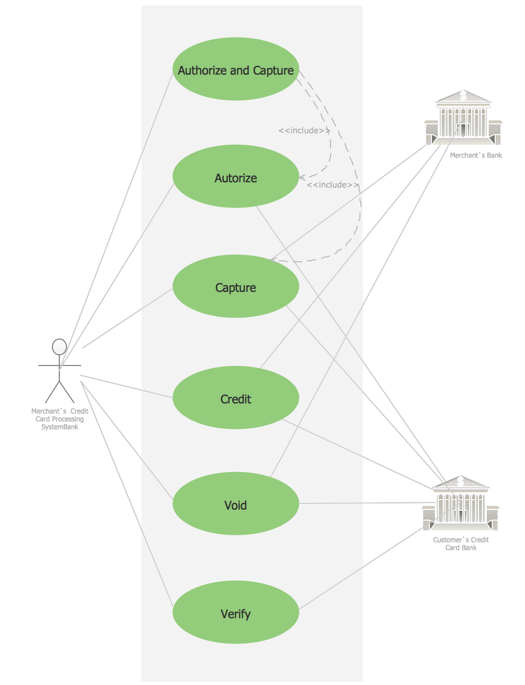
Credit Card Processing System UML Diagram
UML Collaboration Diagram. Design Elements

ConceptDraw has 393 vector stencils in the 13 libraries that helps you to start using software for designing your own UML Diagrams. You can use the appropriate stencils of UML notation from UML Collaboration library with 36 objects
Data Flow Diagram

- Diagram On Business Transactions
- Diagram Showing Business Transaction
- Business Transaction Flow Chart
- Flow Chart Diagrams For Business Transactions
- Diagram Of A Sample Business Transaction
- Business Process Diagrams | ConceptDraw PRO ER Diagram Tool ...
- Business Modeling Diagram For Atm Transaction
- Flowchart During A Transaction In A Business
- Steps in the Accounting Process | Steps of Accounting Cycle | How ...
- Er Diagram For A Banking Transaction System
- Erd Business Transaction
- UML deployment diagram - Real estate transactions | Work Order ...
- Transaction Flows In Business Process Service
- 4 Level pyramid model diagram - Information systems types ...
- UML Activity Diagram | ATM UML Diagrams | ATM Solutions | Draw ...
- Trading process diagram - Deployment flowchart | UML Component ...
- Purpose Of Transaction With An Example Diagram
- Diagram Sales Transaction
- UML deployment diagram - Real estate transactions | Databases ...
- What is the Accounting Cycle?
- ERD | Entity Relationship Diagrams, ERD Software for Mac and Win
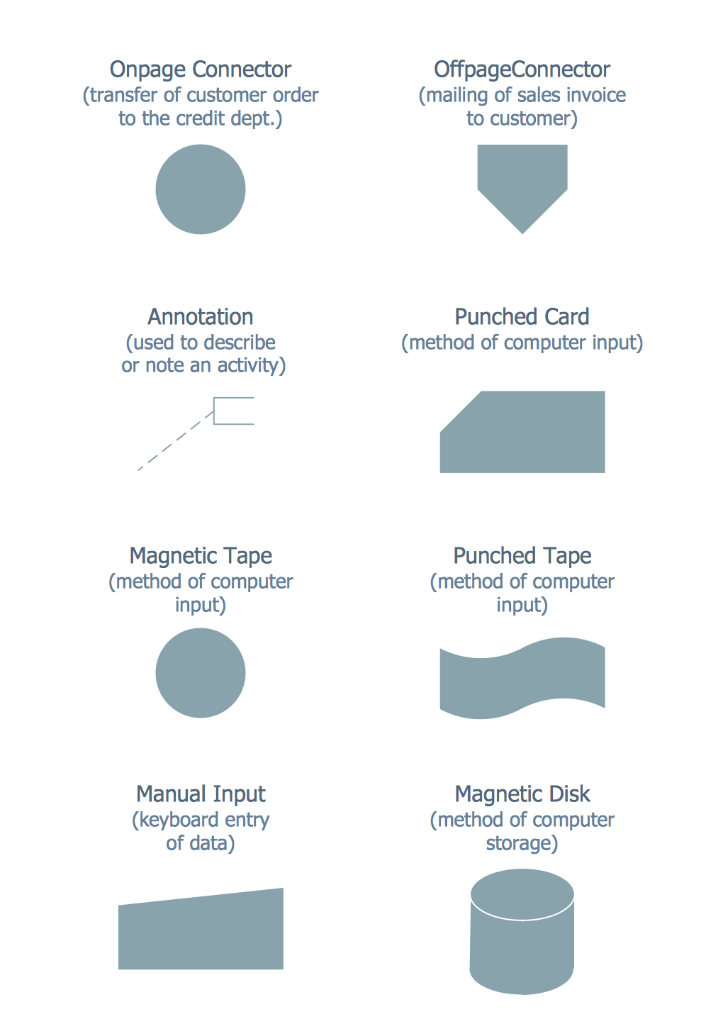
- Flowchart | Basic Flowchart Symbols and Meaning
- Flowchart | Flowchart Design - Symbols, Shapes, Stencils and Icons
- Flowchart | Flow Chart Symbols
- Electrical | Electrical Drawing - Wiring and Circuits Schematics
- Flowchart | Common Flowchart Symbols
- Flowchart | Common Flowchart Symbols