SSADM Diagram

The example below illustrates the waterfall model used in SSADM. This model involves 5 stages of developing a product such as requirements specification and its' analysis, design, coding and testing.
Structured Systems Analysis and Design Method (SSADM) with ConceptDraw DIAGRAM

Software and Database Design with ConceptDraw DIAGRAM

UML diagramming; designing and prototyping Graphical User Interface (GUI); flowcharts, data flow diagrams; database and ERD diagramming (Chen ERD, Database Model diagram, Express-G, Martin ERD, ORM Diagrams and more); SSADM diagrams, Booch diagrams, Nassi-Shneiderman diagrams with special flowchart symbols.
Data Flow Diagram

Software Diagram Examples and Templates

Software Development area of ConceptDraw Solution Park provides 5 solutions:
Data Flow Diagrams, Entity-Relationship Diagram (ERD), Graphic User Interface, IDEFO Diagrams, Rapid UML.
ConceptDraw DIAGRAM Database Modeling Software

ERD Symbols and Meanings

The Chen's ERD notation is still used and is considered to present a more detailed way of representing entities and relationships.
To create an ERD, software engineers mainly turn to dedicated drawing software, which contain the full notation resources for their specific database design - ERD symbols and meanings. CS Odessa has released an all-inclusive Entity-Relationship Diagram (ERD) solution for their powerful drawing program, ConceptDraw DIAGRAM.

ConceptDraw DIAGRAM DFD Software

"In software engineering, an entity–relationship model (ER model) is a data model for describing a database in an abstract way. ...
Crow's Foot notation is used in Barker's Notation, SSADM and Information Engineering. Crow's Foot diagrams represent entities as boxes, and relationships as lines between the boxes. Different shapes at the ends of these lines represent the cardinality of the relationship." [Entity–relationship model. Wikipedia]
This ERD example was redesigned using the ConceptDraw PRO diagramming and vector drawing software from the educational data base model. [www2.cs.uregina.ca/ ~bernatja/ crowsfoot.html]
The example "Entity-relationship diagram (Crow's foot notation)" is included in the Entity-Relationship Diagram (ERD) solution from the Software Development area of ConceptDraw Solution Park.
Crow's foot ERD
.png--diagram-flowchart-example.png)
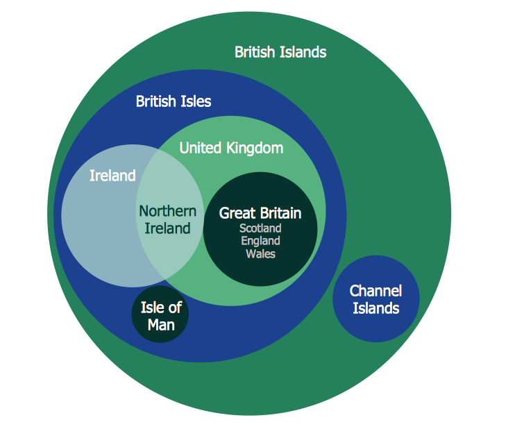
Venn Diagram Examples for Problem Solving. Environmental Social Science. Human Sustainability Confluence

Create your Venn diagrams for problem solving in environmental social science using the ConceptDraw DIAGRAM diagramming and vector drawing software extended with the Venn Diagrams solution from the area "Diagrams" of ConceptDraw Solution Park.
Venn Diagram Template for Word

Cylinder Venn Diagram
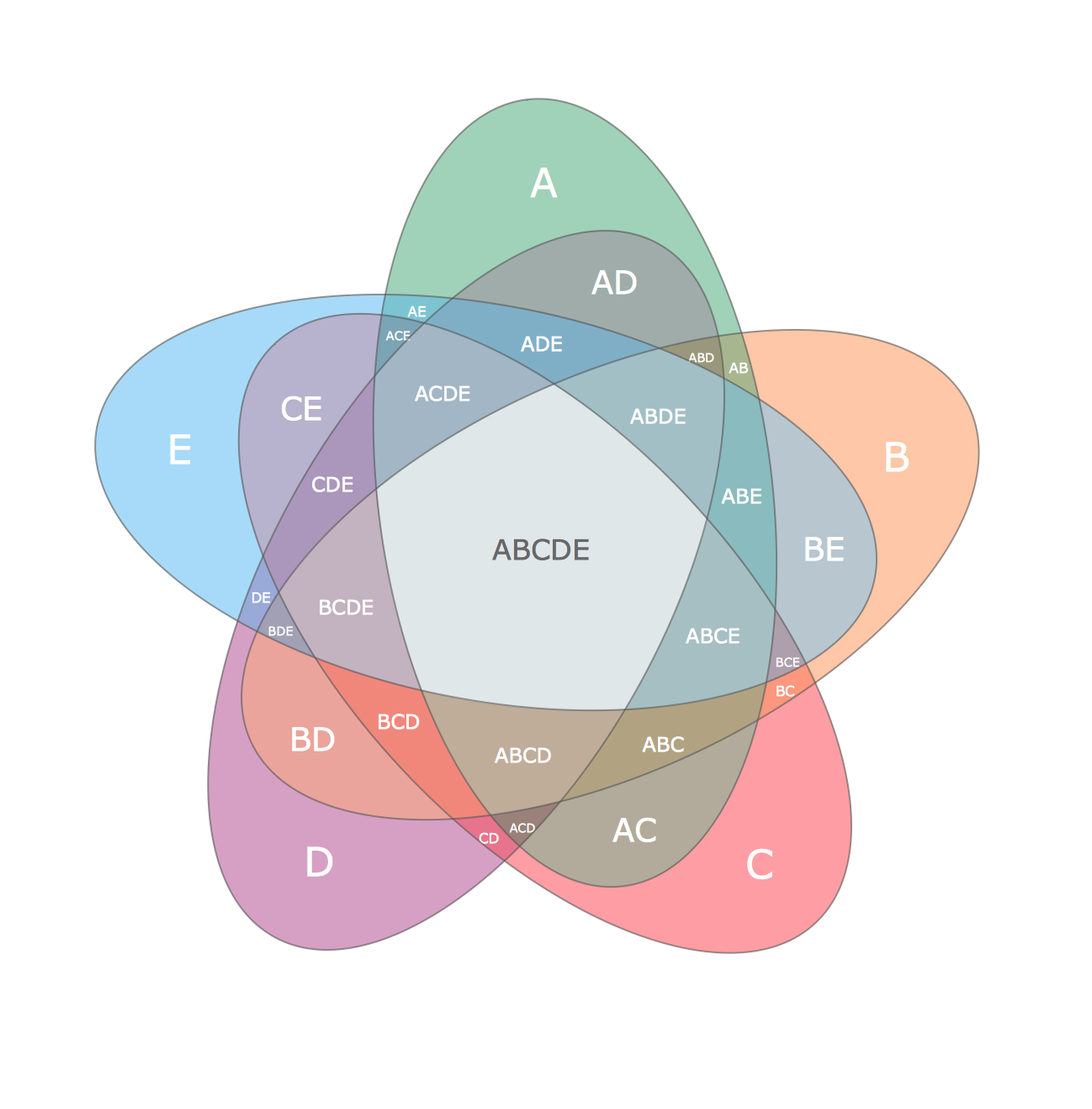
Multi Layer Venn Diagram. Venn Diagram Example
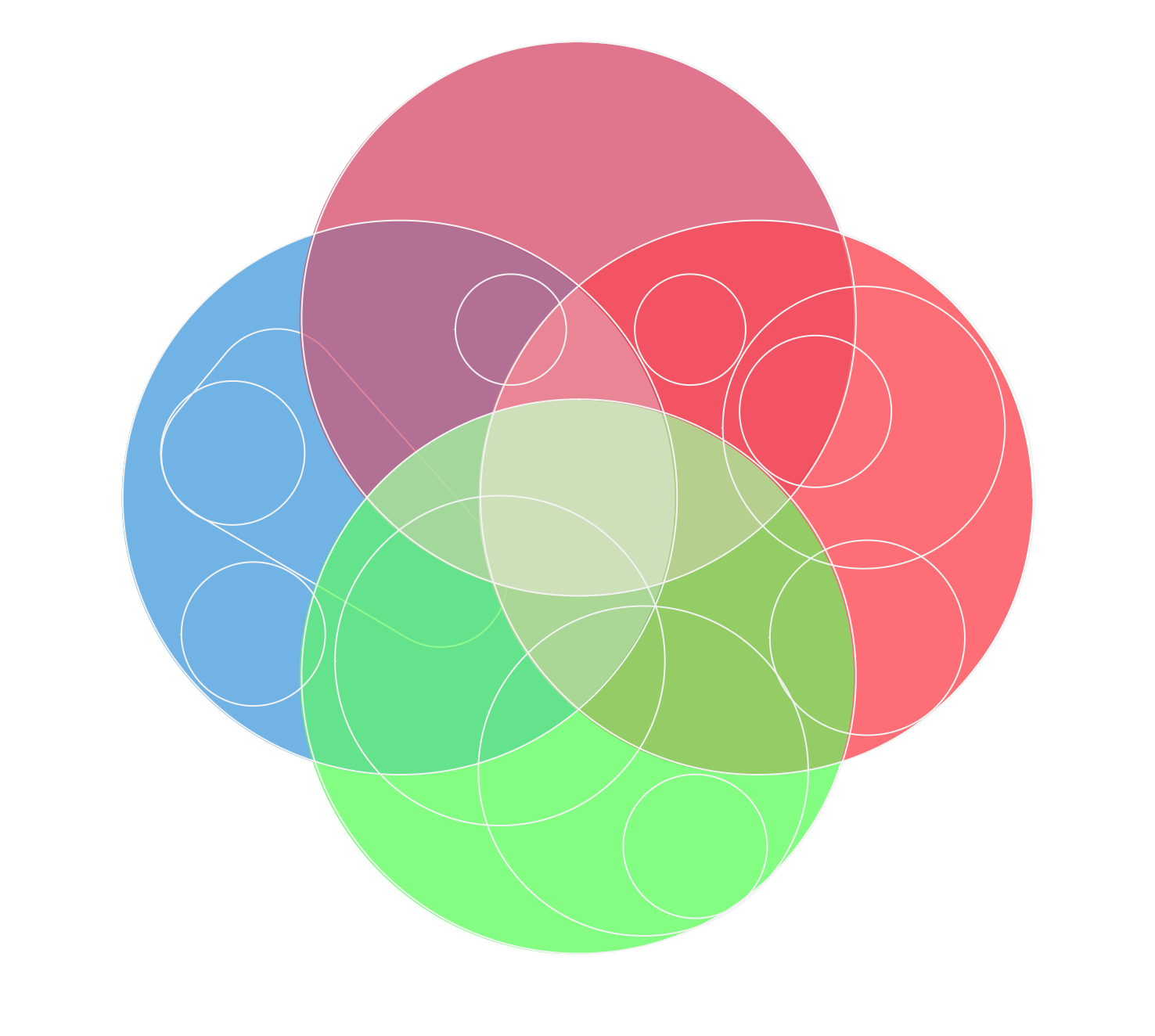
Circles Venn Diagram
- Structured Systems Analysis and Design Method ( SSADM ) with ...
- Structured Systems Analysis and Design Method ( SSADM ) with ...
- Data Flow Diagram Model | Structured Systems Analysis and Design ...
- Structured Systems Analysis and Design Method ( SSADM ) with ...
- Data Flow Diagram (DFD) | Structured Systems Analysis and Design ...
- ORM Diagram | Software Diagram Examples and Templates ...
- SSADM Diagram | Ssadm Waterfall
- Create Block Diagram | Block Diagrams | SSADM Diagram | System ...
- SSADM Diagram | Structured Systems Analysis and Design Method ...
- SSADM Diagram | Draw Flowcharts with ConceptDraw | Yourdon ...
- Data Flow Diagram Ppt For Event Management System
- Process Flowchart | IDEF0 Diagrams | Structured Systems Analysis ...
- Booch OOD Diagram | IDEF0 Diagram | SSADM Diagram | Booch ...
- SSADM Diagram | Software Diagram Examples and Templates ...
- Structured Systems Analysis and Design Method ( SSADM ) with ...
- Data Flow Diagrams In Ssadm
- Structured Systems Analysis and Design Method ( SSADM ) with ...
- SSADM Diagram | Flowcharts | Process Flowchart | Softwarw ...
- Basic Diagramming | Collaboration in a Project Team | SSADM ...
- Basic Diagramming | SSADM Diagram | Yourdon and Coad ...
- ERD | Entity Relationship Diagrams, ERD Software for Mac and Win
- Flowchart | Basic Flowchart Symbols and Meaning
- Flowchart | Flowchart Design - Symbols, Shapes, Stencils and Icons
- Flowchart | Flow Chart Symbols
- Electrical | Electrical Drawing - Wiring and Circuits Schematics
- Flowchart | Common Flowchart Symbols
- Flowchart | Common Flowchart Symbols