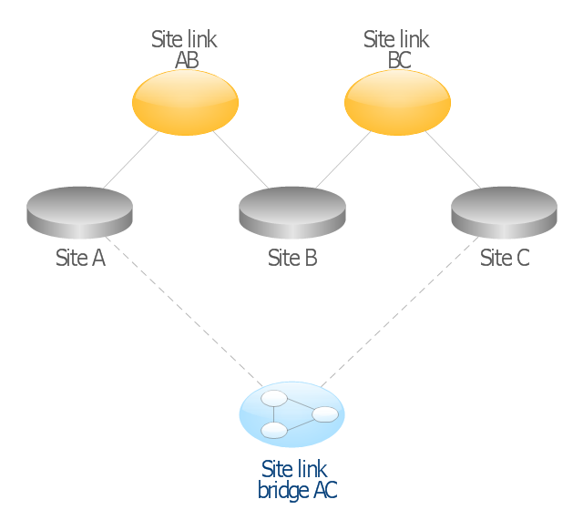
This AD diagram example was redesigned from the picture "Site links" from the book "Active Directory for Dummies".
"Site links represent the Active Directory replication paths between sites.
These paths are manually defined so that the designer has control over which network links the replication traffic occurs on. These site links also control how clients are directed to domain controllers when there’s no DC in the client’s local site. Each site link has the following attributes:
(1) Connected sites: A site link is defined by the sites to which it connects. A site link can connect two or more sites together.
(2) Network transport: Site links support replication communication over IP-based RPCs or with the Simple Mail Transport Protocol (SMTP). You normally want to use RPC whenever possible, but you can use SMTP when the sites you’re linking don’t support RPC.
(3) Cost: Each site link has a cost associated with it. Costs are used to assign preferences to links that determine which link should be followed when multiple link paths are available between sites. The cost represents what it “costs” to use this site link relative to the other site links and affects replication traffic as well as how users are assigned a domain controller. Links with lower cost values have preference over links with higher cost values. Cost values range from 1–32,767; the default being 100.
(4) Frequency: The frequency value defines how often a replication occurs
when using this site link (the replication latency). You can configure the time between replications from a minimum of 15 minutes to a maximum of 10,080 minutes (one week). The default frequency is 180 minutes.
(5) Schedule: The schedule dictates when this link is active and available for replication between the sites. The schedule can also control which days of the week the link is available. Normally, the schedule is set so that the link is available 24 hours a day, but you can set up different schedules on a per-day-of-the-week basis.
By creating a site link, you enable two or more sites to be connected and to share the same site link attributes (transport, cost, frequency, and schedule). By default, site links create transitive connectivity between sites.
If you create a site link between sites A and B and another site link between
sites B and C, an automatic connection (known as a site link bridge) is created between sites A and C..." [Steve Clines and Marcia Loughry, Active Directory® For Dummies®, 2nd Edition. 2008]
The Active Directory diagram example "Site links" was created using the ConceptDraw PRO diagramming and vector drawing software extended with the Active Directory Diagrams solution from the Computer and Networks area of ConceptDraw Solution Park.
Active Directory network diagram
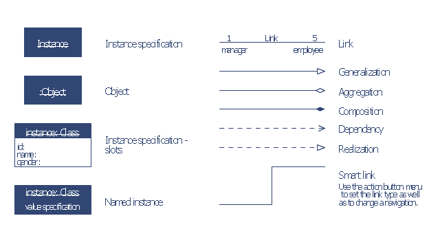
The vector stencils library "Bank UML object diagram" contains 11 shapes for drawing UML object diagrams.
Use it for object-oriented modeling of your bank information system.
"In the Unified Modeling Language (UML), an object diagram focuses on some particular set of objects and attributes, and the links between these instances. A correlated set of object diagrams provides insight into how an arbitrary view of a system is expected to evolve over time. ...
Each object and link on an object diagram is represented by an InstanceSpecification. This can show an object's classifier (e.g. an abstract or concrete class) and instance name, as well as attributes and other structural features using slots. Each slot corresponds to a single attribute or feature, and may include a value for that entity. ...
The name on an instance specification optionally shows an instance name, a ':' separator, and optionally one or more classifier names separated by commas. The contents of slots, if any, are included below the names, in a separate attribute compartment. A link is shown as a solid line, and represents an instance of an association. ...
An object instance may be called an instance specification or just an instance. A link between instances is generally referred to as a link. Other UML entities, such as an aggregation or composition symbol (a diamond) may also appear on an object diagram." [Object diagram. Wikipedia]
This example of UML object diagram symbols for the ConceptDraw PRO diagramming and vector drawing software is included in the ATM UML Diagrams solution from the Software Development area of ConceptDraw Solution Park.
UML object diagram symbols
HelpDesk
How to Create a Rack Diagram

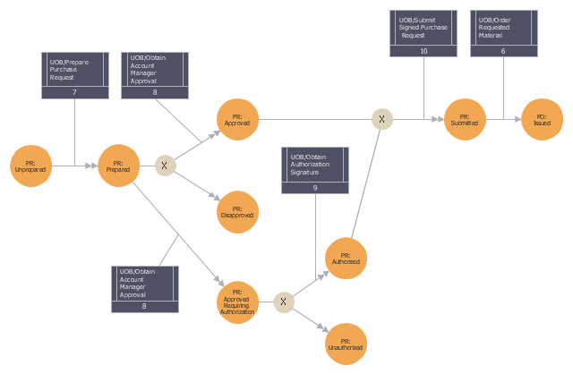
This IDEF3 diagram example was redesigned from the Wikimedia Commons file: 5-21 Completed Transition Schematic.jpg.
[commons.wikimedia.org/ wiki/ File:5-21_ Completed_ Transition_ Schematic.jpg]
"As with the Process Schematic, the correctness of the Object Schematic and
associated elaborations are confirmed through validation with the domain expert. After reviewing the Transition Schematic, the domain expert observes that the allowable state transitions displayed in the schematic do not include those representative of a failed request. ...
The domain expert also identified transitions through which the identity of the object was preserved and transitions where the object was actually transformed into an entirely different object. The domain expert’s comments to the analyst yield the schematic
depicted in Figure 5-21." [IDEF3 Process Description Capture Method Report AL-TR-1995-XXXX. idef.com/ pdf/ Idef3_ fn.pdf]
The sample "Completed transition schematic - IDEF3 diagram" was created using the ConceptDraw PRO diagramming and vector drawing software extended with the solution "IDEF Business Process Diagrams" from the area "Business Processes" of ConceptDraw Solution Park.
IDEF3 business process diagram
Bubble diagrams in Landscape Design with ConceptDraw DIAGRAM

Garrett IA Diagrams with ConceptDraw DIAGRAM

This IDEF3 diagram example was redesigned from the Wikimedia Commons file: 2-03 Example of an Enhanced Transition Schematic.jpg.
[en.wikipedia.org/ wiki/ File:2-03_ Example_ of_ an_ Enhanced_ Transition_ Schematic.jpg]
"IDEF3 descriptions are developed from two different perspectives: process-centered and object-centered. Because these approaches are not mutually exclusive, IDEF3 allows cross-referencing between them to represent complex process descriptions." [IDEF3. Wikipedia]
The IDEF3 diagram example "Enhanced transition schematic" was created using the ConceptDraw PRO diagramming and vector drawing software extended with the solution "IDEF Business Process Diagrams" from the area "Business Processes" of ConceptDraw Solution Park.
IDEF3 business process diagram
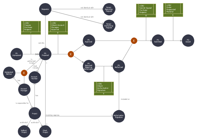
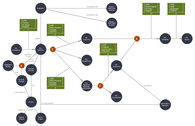
This IDEF3 diagram example was redesigned from the Wikimedia Commons file: 5-22 Final Object Schematic.jpg.
[commons.wikimedia.org/ wiki/ File:5-22_ Final_ Object_ Schematic.jpg]
"Additional context-setting information is then added to the Transition Schematic as required. For example, the domain expert’s description indicated that purchase requests involving direct projects require an authorization signature. Additionally, the description included discussion of a constraint that account managers or their designated backups must approve all requests involving their projects. This information is noted directly on the schematic. The resulting Object Schematic is displayed in Figure 5-22." [IDEF3 Process Description Capture Method Report AL-TR-1995-XXXX. idef.com/ pdf/ Idef3_ fn.pdf]
The sample "Final object schematic - IDEF3 diagram" was created using the ConceptDraw PRO diagramming and vector drawing software extended with the solution "IDEF Business Process Diagrams" from the area "Business Processes" of ConceptDraw Solution Park.
IDEF3 business process diagram
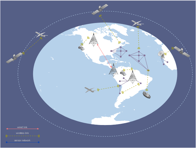
A conceptual diagram of a global vehicular network describes the principles of communication between vehicles, earth-based nodes, and space-based nodes in a wireless network. It illustrates the concept of architecture within global vehicular networks.
"Intelligent transportation systems (ITS) are advanced applications which, without embodying intelligence as such, aim to provide innovative services relating to different modes of transport and traffic management and enable various users to be better informed and make safer, more coordinated, and 'smarter' use of transport networks.
...
Intelligent transport systems vary in technologies applied, from basic management systems such as car navigation; traffic signal control systems; container management systems; variable message signs; automatic number plate recognition or speed cameras to monitor applications, such as security CCTV systems; and to more advanced applications that integrate live data and feedback from a number of other sources, such as parking guidance and information systems; weather information; bridge deicing systems; and the like." [Intelligent transportation system. Wikipedia]
The global vehicular network diagram template is included in the Vehicular Networking solution from the Computer and Networks area of ConceptDraw Solution Park.
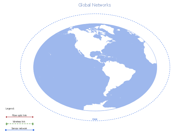
Global vehicular network diagram template
This global vehicular network diagram sample represents the independent regional telematics network.
"Telematics typically is any integrated use of telecommunications and informatics, also known as ICT (Information and Communications Technology). Hence the application of telematics is with any of the following:
(1) The technology of sending, receiving and storing information via telecommunication devices in conjunction with affecting control on remote objects.
(2) The integrated use of telecommunications and informatics, for application in vehicles and with control of vehicles on the move.
(3) Telematics includes but is not limited to Global Positioning System technology integrated with computers and mobile communications technology in automotive navigation systems. ...
Practical applications of vehicle telematics:
1. Vehicle tracking is a way of monitoring the location, movements, status and behaviour of a vehicle or fleet of vehicles. ...
2. Trailer tracking is the technology of tracking the movements and position of an articulated vehicle's trailer unit...
3. Container tracking. Freight containers can be tracked by GPS...
4. Cold store freight trailers ... used to deliver fresh or frozen foods are ... incorporating telematics to gather time-series data on the temperature inside the cargo container...
5. Fleet management includes the management of ships and or motor vehicles such as cars, vans and trucks. Fleet ... Management can include ... vehicle telematics (tracking and diagnostics)...
6. Satellite navigation in the context of vehicle telematics is the technology of using a GPS and electronic mapping tool to enable the driver of a vehicle to locate a position, plan a route and navigate a journey.
7. Mobile data is the use of wireless data communications using radio waves to send and receive real time computer data to, from and between devices used by field based personnel. ...
8. Wireless vehicle safety communications telematics aid in car safety and road safety. ...
9. Emergency warning system for vehicles. Telematics ... are self-orientating open network architecture structures of variable programmable intelligent beacons ... to accord ... warning information with surrounding vehicles in the vicinity of travel, intra-vehicle, and infrastructure. ...
10. Intelligent vehicle technologies. Telematics comprise electronic ... devices ... to provide precision repeatability functions ... emergency warning validation performance reconstruction. ...
11. Car clubs. Telematics-enabled computers allow organizers to track members' usage and bill them on a pay-as-you-drive basis. ...
12. Auto insurance. The basic idea of telematic auto insurance is that a driver's behavior is monitored directly while the person drives and this information is transmitted to an insurance company." [Telematics. Wikipedia]
The example "Independent regional networks diagram" was created using the ConceptDraw PRO diagramming and vector drawing software extended with the Vehicular Networking solution from the Computer and Networks area of ConceptDraw Solution Park.
Global vehicular network diagram
- Telecommunication Network Diagrams | Design elements ...
- Active Directory diagram - Site links | UML Use Case Diagram ...
- Communication network diagram | Telecommunication Network ...
- Active Directory diagram - Site links | How to Edit a Project Task List ...
- Active Directory diagram - Site links | Fully Connected Network ...
- Active Directory Diagram | Active Directory diagram - Site links ...
- Active Directory diagram - Site links | Road Transport - Design ...
- Fully Connected Network Topology Diagram | Overlay network ...
- Satellite telecom network diagram | Global networks - Vector stencils ...
- Active Directory Diagram
- Radio Link Diagrams
- Activity Diagrams For Wireless Setup Link
- Link Diagram Software Free
- Active Directory for Network Diagrams
- Fully Connected Network Topology Diagram | Calculate The ...
- Active Directory diagram - Site links
- Diagram Of Link And Node In Data Communication
- Link Diagram Software
- Fully Connected Network Topology Diagram | Local area network ...
- Diagram Of Link In Data Communication
- ERD | Entity Relationship Diagrams, ERD Software for Mac and Win
- Flowchart | Basic Flowchart Symbols and Meaning
- Flowchart | Flowchart Design - Symbols, Shapes, Stencils and Icons
- Flowchart | Flow Chart Symbols
- Electrical | Electrical Drawing - Wiring and Circuits Schematics
- Flowchart | Common Flowchart Symbols
- Flowchart | Common Flowchart Symbols