UML Diagram

Create unified modeling language (UML) diagrams with ConceptDraw.
HelpDesk
How to Create an Object-Role Modeling (ORM) Diagram
 Diagram")
HelpDesk
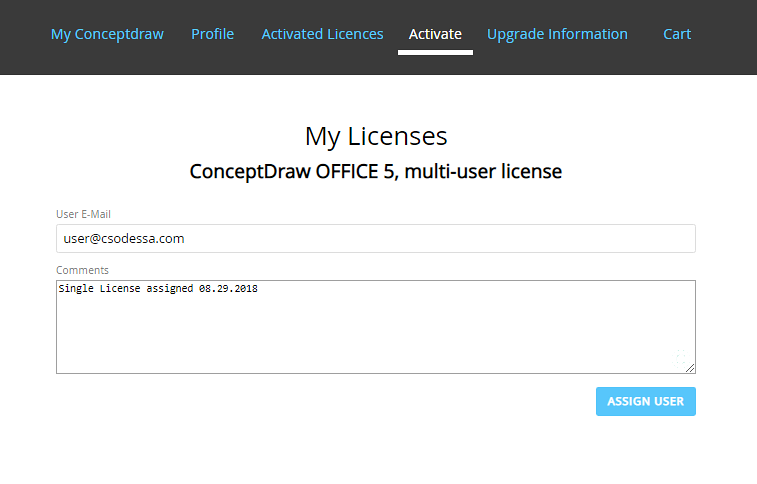
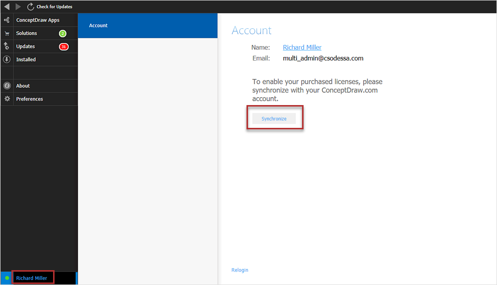
How to Manage ConceptDraw Multi-User License
Software and Database Design with ConceptDraw DIAGRAM

UML diagramming; designing and prototyping Graphical User Interface (GUI); flowcharts, data flow diagrams; database and ERD diagramming (Chen ERD, Database Model diagram, Express-G, Martin ERD, ORM Diagrams and more); SSADM diagrams, Booch diagrams, Nassi-Shneiderman diagrams with special flowchart symbols.
Diagram of a Basic Computer Network. Computer Network Diagram Example

This sample shows the connection scheme of the home WLAN equipment to the Internet.
HelpDesk
How to Add a Telecommunication Network Diagram to a PowerPoint Presentation

HelpDesk
How to Activate ConceptDraw Purchased Through Reseller
HelpDesk
How to Draw a Decision-Making Diagram

Software Diagram Examples and Templates

Software Development area of ConceptDraw Solution Park provides 5 solutions:
Data Flow Diagrams, Entity-Relationship Diagram (ERD), Graphic User Interface, IDEFO Diagrams, Rapid UML.
Business Process Flowchart Symbols

- Login and registration processing | Login and registration ...
- Diagram Activate Account
- UML activity diagram - User registration | Rapid UML | ATM UML ...
- Flowchart | UML Use Case Diagram Example Registration System ...
- UML activity diagram - User registration | Diagramming Software for ...
- How to Activate ConceptDraw After Purchasing from the Web Store ...
- UML activity diagram - User registration | UML Use Case Diagram ...
- Use Case Diagram Of Safe Home
- IDEF3 Standard | How to create an IDEF3 diagram using ...
- Account Opening Procedure In Flow Chart
- ERD | Entity Relationship Diagrams, ERD Software for Mac and Win
- Flowchart | Basic Flowchart Symbols and Meaning
- Flowchart | Flowchart Design - Symbols, Shapes, Stencils and Icons
- Flowchart | Flow Chart Symbols
- Electrical | Electrical Drawing - Wiring and Circuits Schematics
- Flowchart | Common Flowchart Symbols
- Flowchart | Common Flowchart Symbols