Taxi Service Data Flow Diagram DFD Example

UML Use Case Diagram Example - Taxi Service

This sample shows the work of the taxi service and is used by taxi stations, by airports, in the tourism field and delivery service.
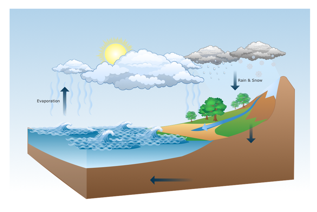
Drawing a Nature Scene
Examples of Flowcharts, Org Charts and More


UML Package Diagram. Design Elements

ConceptDraw has 393 vector stencils in the 13 libraries that helps you to start using software for designing your own UML Diagrams. You can use the appropriate stencils of UML notation from UML Package library.
Network Topology Mapper

Network Topology Mapper offers extensive drawing tools professional-looking network diagrams quickly and easily allowing you to clearly represent and communicate network architecture, topology, and design to engineers, stakeholders and end-users.
Work Order Process Flowchart. Business Process Mapping Examples
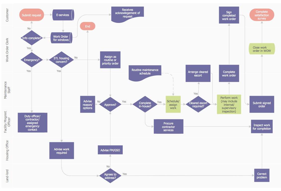
The cross-functional flow chart example shows business process mapping of the real property work order.
Cisco IBM. Cisco icons, shapes, stencils and symbols

Entity-Relationship Diagram (ERD) with ConceptDraw DIAGRAM

one-to-many, many-to-many.
Draw Entity-Relationship Diagrams (ERD) easily with ConceptDraw extended with Entity-Relationship Diagram (ERD) Solution from the Software Development Area. Use ERD software to create ER diagram.

 Specification and Description Language (SDL)
For people in the field of systems engineering or system design, working with specification and description language (sdl) and finite state machines (fsm).
- Dfd Example For Airport Management System
- Data Flow Diagram For Airport Management System
- Composite Structure Diagram For Hotel Management System
- Taxi Service Data Flow Diagram DFD Example | UML Use Case ...
- Rapid UML | Business Process Modeling Tools | Taxi service order ...
- City Bus Dfd Diagram
- Taxi Service Data Flow Diagram DFD Example | Business Process ...
- Bpmn Diagram For Hotel Management System
- Class Diagram For Hotel Management System
- Activity Diagram For Airport
- ERD | Entity Relationship Diagrams, ERD Software for Mac and Win
- Flowchart | Basic Flowchart Symbols and Meaning
- Flowchart | Flowchart Design - Symbols, Shapes, Stencils and Icons
- Flowchart | Flow Chart Symbols
- Electrical | Electrical Drawing - Wiring and Circuits Schematics
- Flowchart | Common Flowchart Symbols
- Flowchart | Common Flowchart Symbols