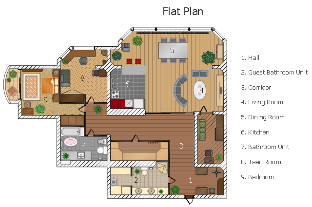
This flat design floor plan sample shows layout of furniture, kitchen equipment and bathroom appliance.
"An apartment (in American English) or flat in British English is a self-contained housing unit (a type of residential real estate) that occupies only part of a building. Such a building may be called an apartment building, apartment house (in American English), block of flats, tower block, high-rise or, occasionally mansion block (in British English), especially if it consists of many apartments for rent. In Scotland it is often called a tenement, which has a pejorative connotation elsewhere. Apartments may be owned by an owner/ occupier by leasehold tenure or rented by tenants (two types of housing tenure).
Apartments can be classified into several types. In North America the typical terms are a studio, efficiency or bachelor apartment (bedsit in the UK). These all tend to be the smallest apartments with the cheapest rents in a given area. This kind of apartment usually consists mainly of a large room which is the living, dining and bedroom combined. There are usually kitchen facilities as part of this central room, but the bathroom is a separate, smaller room.
Moving up from the bachelors/ efficiencies are one-bedroom apartments, in which one bedroom is separate from the rest of the apartment. Then there are two-bedroom, three-bedroom, etc. apartments. Small apartments often have only one entrance.
Large apartments often have two entrances, perhaps a door in the front and another in the back. Depending on the building design, the entrance doors may be directly to the outside or to a common area inside, such as a hallway. Depending on location, apartments may be available for rent furnished with furniture or unfurnished into which a tenant moves in with their own furniture." [Apartment. Wikipedia]
The example "Flat design floor plan" was created using the ConceptDraw PRO diagramming and vector drawing software extended with the Floor Plans solution from the Building Plans area of ConceptDraw Solution Park.
Interior design
 Floor Plans
Construction, repair and remodeling of the home, flat, office, or any other building or premise begins with the development of detailed building plan and floor plans. Correct and quick visualization of the building ideas is important for further construction of any building.
Diagramming Software for Design UML Collaboration Diagrams


UML Collaboration Diagram. Design Elements

ConceptDraw has 393 vector stencils in the 13 libraries that helps you to start using software for designing your own UML Diagrams. You can use the appropriate stencils of UML notation from UML Collaboration library with 36 objects
Entity Relationship Diagram Symbols

ERD symbols used for professional ERD drawing are collected in libraries from the Entity-Relationship Diagram (ERD) solution for ConceptDraw DIAGRAM.
UML State Machine Diagram.Design Elements

ConceptDraw has 393 vector stencils in the 13 libraries that helps you to start using software for designing your own UML Diagrams. You can use the appropriate stencils of UML notation from UML State Machine library.
Business - Design Elements
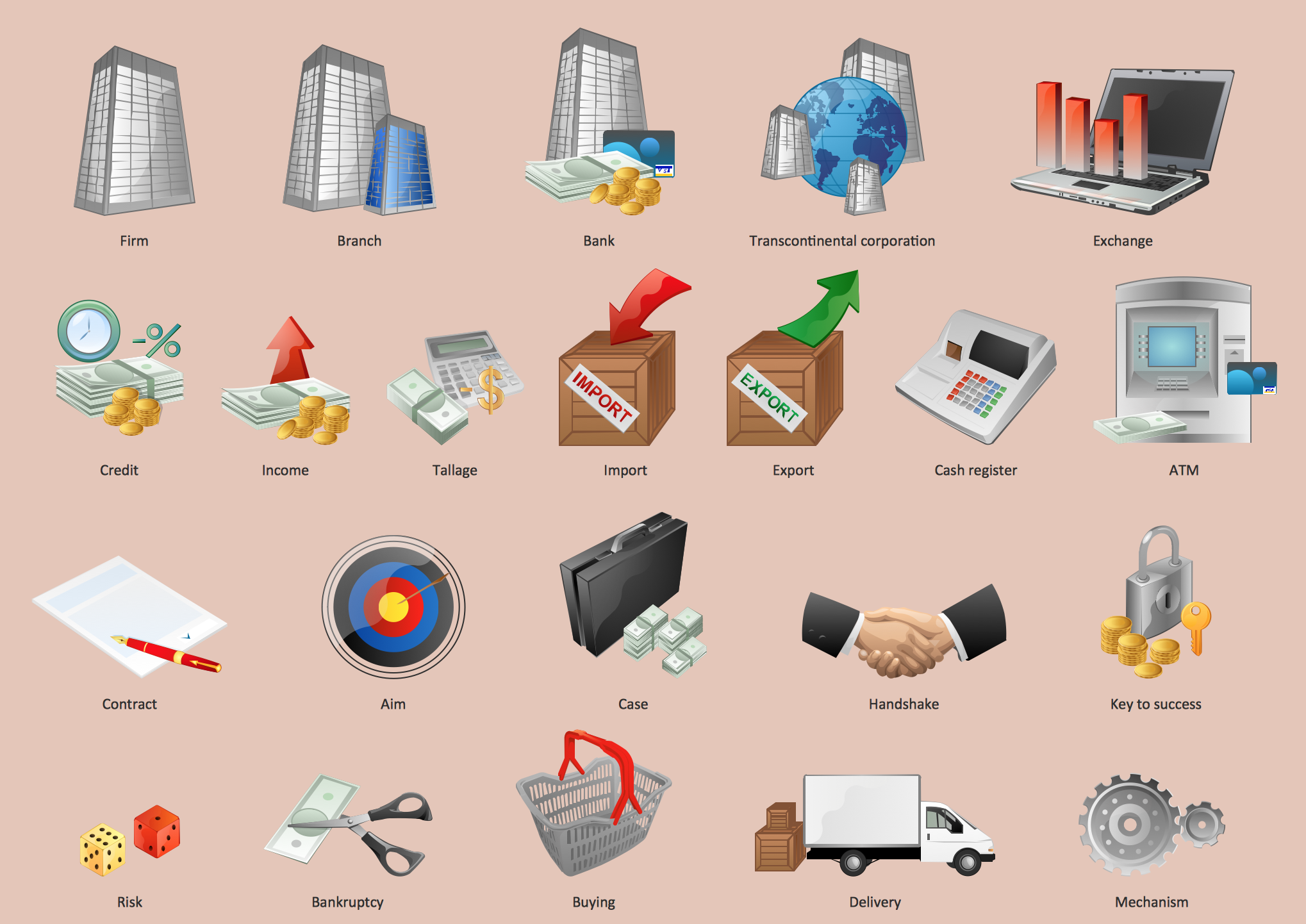
Design your own style with Business and Finance Solutions from ConceptDraw DIAGRAM.
We created a full set of elements, business samples, templates and libraries with vector clip art for drawing the Business Illustrations.
Mark your report or presentation, pay an attention of audience on your drawings with vector business design elements.
Data Flow Diagram

Building Drawing Software for Design Site Plan


 Computer Network Diagrams
Computer Network Diagrams solution extends ConceptDraw DIAGRAM software with samples, templates and libraries of vector icons and objects of computer network devices and network components to help you create professional-looking Computer Network Diagrams, to plan simple home networks and complex computer network configurations for large buildings, to represent their schemes in a comprehensible graphical view, to document computer networks configurations, to depict the interactions between network's components, the used protocols and topologies, to represent physical and logical network structures, to compare visually different topologies and to depict their combinations, to represent in details the network structure with help of schemes, to study and analyze the network configurations, to communicate effectively to engineers, stakeholders and end-users, to track network working and troubleshoot, if necessary.
- Building Plan For A Room Self Contained
- Flat design floor plan | One Room Self Contained House Plan
- Floor Plan Of A Self Contain One Room
- One Room Self Contained Plan
- Self Contained Room And Parlor Apartment Design With Photos
- Electrical Installation Design For Three Rooms Self Contain
- Wiring Diagram For Three Bed Room Self Contain
- One Room Self Contain Design
- Different Floor Plan Designs For Room And Palor Self Contain
- Network Topologies | House Plans For A Single Self Contained Room
- ERD | Entity Relationship Diagrams, ERD Software for Mac and Win
- Flowchart | Basic Flowchart Symbols and Meaning
- Flowchart | Flowchart Design - Symbols, Shapes, Stencils and Icons
- Flowchart | Flow Chart Symbols
- Electrical | Electrical Drawing - Wiring and Circuits Schematics
- Flowchart | Common Flowchart Symbols
- Flowchart | Common Flowchart Symbols