Entity Relationship Diagram Symbols

ERD symbols used for professional ERD drawing are collected in libraries from the Entity-Relationship Diagram (ERD) solution for ConceptDraw DIAGRAM.
Basic Flowchart Symbols and Meaning


Process Flowchart


ERD Symbols and Meanings

The Chen's ERD notation is still used and is considered to present a more detailed way of representing entities and relationships.
To create an ERD, software engineers mainly turn to dedicated drawing software, which contain the full notation resources for their specific database design - ERD symbols and meanings. CS Odessa has released an all-inclusive Entity-Relationship Diagram (ERD) solution for their powerful drawing program, ConceptDraw DIAGRAM.

Process Flow Chart Symbols
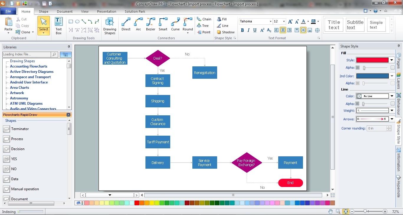
It is incredibly convenient to use the ConceptDraw DIAGRAM software extended with Flowcharts Solution from the "Diagrams" Area of ConceptDraw Solution Park for designing professional looking Process Flow Charts.
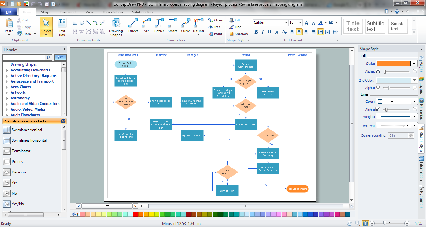
Cross Functional Flowchart
UML Block Diagram

This sample shows the work of the taxi service and is used by taxi stations, by airports, in the tourism field and delivery service.
Swim Lane Flowchart Symbols

UML Class Diagram Generalization Example UML Diagrams

This sample describes the use of the classes, the generalization associations between them, the multiplicity of associations and constraints. Provided UML diagram is one of the examples set that are part of Rapid UML solution.
Create Flow Chart on Mac
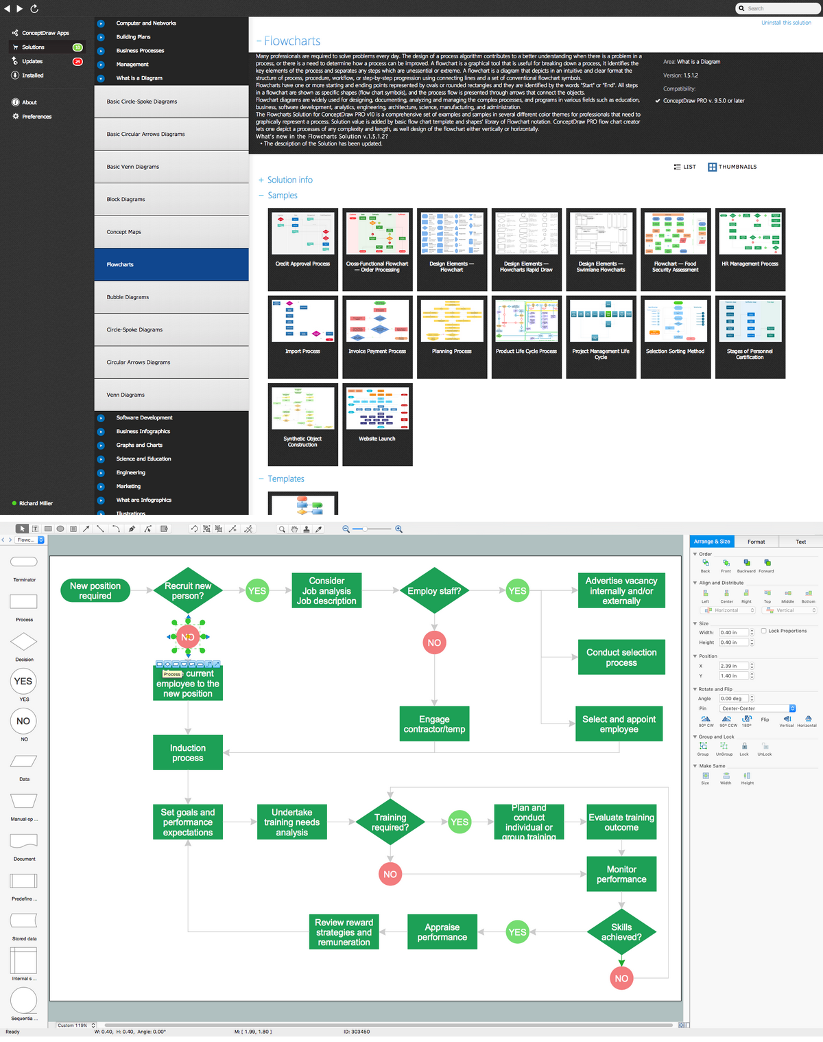
Extended flowchart maker features of Rapid Draw functionality was developed to create flow chart on the Mac OS X platform. You will save time by quick and simple flowchart maker due to Rapid Draw.
- Dependency Management Flow Chart
- Basic Flowchart Symbols and Meaning | Accounting Flowchart ...
- Dependency Symbol In Flowchart
- Basic Flowchart Symbols and Meaning | Sales Flowcharts | Cycle of ...
- Project —Task Trees and Dependencies | Basic Flowchart Symbols ...
- Project —Task Trees and Dependencies | Cycle of automobile ...
- Project —Task Trees and Dependencies | ConceptDraw PRO DFD ...
- Entity Relationship Diagram Symbols | Database Flowchart Symbols ...
- Model Based Systems Engineering | Process Flow Chart Symbols ...
- Flow Diagram With Dependencies
- ERD | Entity Relationship Diagrams, ERD Software for Mac and Win
- Flowchart | Basic Flowchart Symbols and Meaning
- Flowchart | Flowchart Design - Symbols, Shapes, Stencils and Icons
- Flowchart | Flow Chart Symbols
- Electrical | Electrical Drawing - Wiring and Circuits Schematics
- Flowchart | Common Flowchart Symbols
- Flowchart | Common Flowchart Symbols