The vector stencils library Alarm and access control contains 80 symbols of digital proximity equipment, locking hardware, and access control equipment.
"An alarm device or system of alarm devices gives an audible, visual or other form of alarm signal about a problem or condition. Alarm devices are often outfitted with a siren." [Alarm device. Wikipedia]
"An access control point, which can be a door, turnstile, parking gate, elevator, or other physical barrier, where granting access can be electronically controlled. Typically, the access point is a door. An electronic access control door can contain several elements. At its most basic, there is a stand-alone electric lock. The lock is unlocked by an operator with a switch. To automate this, operator intervention is replaced by a reader. The reader could be a keypad where a code is entered, it could be a card reader, or it could be a biometric reader. Readers do not usually make an access decision, but send a card number to an access control panel that verifies the number against an access list. To monitor the door position a magnetic door switch can be used. In concept, the door switch is not unlike those on refrigerators or car doors. Generally only entry is controlled, and exit is uncontrolled. In cases where exit is also controlled, a second reader is used on the opposite side of the door. In cases where exit is not controlled, free exit, a device called a request-to-exit (REX) is used. Request-to-exit devices can be a push-button or a motion detector. When the button is pushed, or the motion detector detects motion at the door, the door alarm is temporarily ignored while the door is opened. Exiting a door without having to electrically unlock the door is called mechanical free egress. This is an important safety feature. In cases where the lock must be electrically unlocked on exit, the request-to-exit device also unlocks the door." [Access control. Wikipedia]
Use the design elements library Alarm and access control for drawing layout floor plans, blueprints, and wiring diagrams of intrusion systems, time and attendance systems, card and code access control security systems, internal and external security control systems using the ConceptDraw PRO diagramming and vector drawing software.
The shapes library Alarm and access control is included in the Security and Access Plans solution from the Building Plans area of ConceptDraw Solution Park.
Alarm and access control symbols

The vector stencils library Initiation and annunciation contains 9 symbols of Fire Alarm Control Panel (FACP) or Fire Alarm Control Unit (FACU) elements, triggering devices, audible alarm systems, timers, security control equipment, and recording devices.
"A Fire Alarm Control Panel (FACP), or Fire Alarm Control Unit (FACU), is the controlling component of a Fire Alarm System. The panel receives information from environmental sensors designed to detect changes associated with fire, monitors their operational integrity and provides for automatic control of equipment, and transmission of information necessary to prepare the facility for fire based on a predetermined sequence. The panel may also supply electrical energy to operate any associated sensor, control, transmitter, or relay. There are four basic types of panels: coded panels, conventional panels, addressable panels, and multiplex systems." [Fire alarm control panel. Wikipedia]
Use the shapes library Initiation and annunciation to draw layout floor plans, communications schematics and wiring diagrams of security systems using the ConceptDraw PRO diagramming and vector drawing software.
The design elements library Initiation and annunciation is included in the Security and Access Plans solution from the Building Plans area of ConceptDraw Solution Park.
Initiation and annunciation symbols

Basic Flowchart Symbols and Meaning


Physical Security Plan

How To use House Electrical Plan Software

You can use many of built-in templates, electrical symbols and electical schemes examples of our House Electrical Diagram Software.
ConceptDraw is a fast way to draw: Electrical circuit diagrams, Schematics, Electrical Wiring, Circuit schematics, Digital circuits, Wiring in buildings, Electrical equipment, House electrical plans, Home cinema, Satellite television, Cable television, Closed-circuit television.
House Electrical Plan Software works across any platform, meaning you never have to worry about compatibility again. ConceptDraw PRO allows you to make electrical circuit diagrams on PC or macOS operating systems.

Home Electrical Plan

Electrical and Telecom Plan Software

Electrical Drawing Software and Electrical Symbols

Electrical Drawing Software provides the 26 stencils libraries of ready-to-use predesigned vector electrical symbols, templates and samples that make your electrical drawing quick, easy and effective.
The vector stencils library "Electrical and telecom" contains 83 symbols of electrical and telecommunication equipment for electrical drawings and wiring diagrams of buildings, communication centers, power plants and electrical distribution systems.
"An electrical drawing, is a type of technical drawing that shows information about power, lighting, and communication for an engineering or architectural project." [Electrical drawing. Wikipedia]
Use the design elements library "Electrical and telecom" to design your own electrical drawings, plot plans of the building outside electrical wiring, floor plans with electrical and telecommunication systems layout, power-riser diagrams with panel boards, control wiring diagrams and cabling layout schemes, reflected ceiling plans and lighting panels layouts using the ConceptDraw PRO diagramming and vector drawing software.
The shapes library "Electrical and telecom" is included in the Electric and Telecom Plans solution from the Building Plans area of ConceptDraw Solution Park.
Electrical and telecom symbols

Electrical Symbols — Delay Elements

26 libraries of the Electrical Engineering Solution of ConceptDraw PRO make your electrical diagramming simple, efficient, and effective. You can simply and quickly drop the ready-to-use objects from libraries into your document to create the electrical diagram.
Electrical Diagram

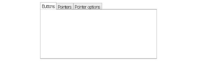
The vector stencils library "Controls" contains 53 icons of Windows 8 controls.
Use it to design graphic user interface (GUI) prototypes of your software applications for Windows 8.
"A graphical control element or widget is an element of interaction in a graphical user interface (GUI), such as a button or a scroll bar. Controls are software components that a computer user interacts with through direct manipulation to read or edit information about an application. ...
Each widget facilitates a specific type of user-computer interaction, and appears as a visible part of the application's GUI as defined by the theme and rendered by the rendering engine. The theme makes all graphical control elements adhere to a unified aesthetic design and creates a sense of overall cohesion. Some widgets support interaction with the user, for example labels, buttons, and check boxes. Others act as containers that group the widgets added to them, for example windows, panels, and tabs." [Graphical control element. Wikipedia]
The design elements example "Controls - Vector stencils library" was created using the ConceptDraw PRO diagramming and vector drawing software extended with the Windows 8 User Interface solution from the Software Development area of ConceptDraw Solution Park.
Balloon

Check box - checked

Check box - unchecked

Radio button - selected

Radio button

Group box

Standard command button

Default command button

Link

Command link - selected

Command link

Command link

Command link 2

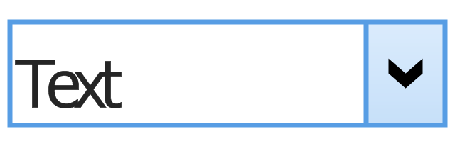
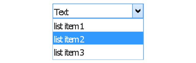
Drop-down button with text box

Drop-down button with text box - selected
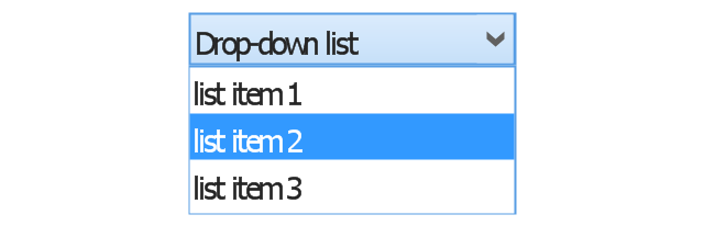
Drop-down list

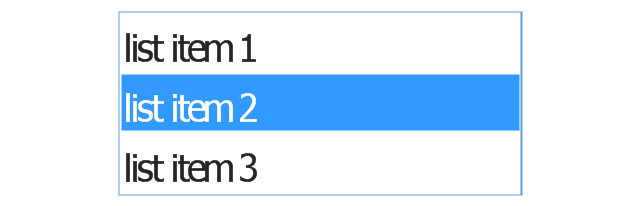
List item

List item - selected

Drop-down button with text box 2

Drop-down list 2

Drop-down button

Drop-down button - selected

Combo box
Combo box 2
Combo box with scroller
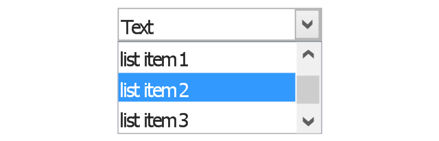
List box
List box with scrollbar
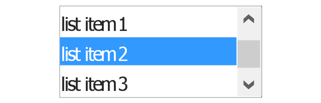
List view
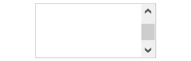
Vertical scroller

Horizontal scroller

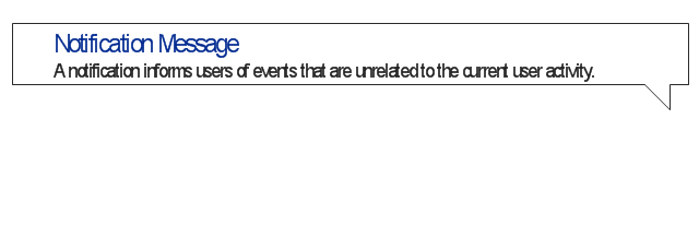
Notification
Options button

Close button

Text label

Progress bar

Search box

Search symbol

Spin control

Slider - 5 intervals
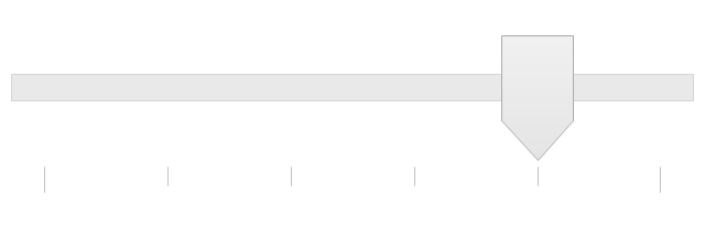
Slider - 10 intervals

Status bar

Start button

Status bar with Start button

Viewed window

Current window state

Tab control

Tab control - selected

Tab view page

Tab view
Text box

Text box label

Tooltip

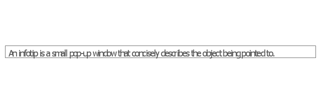
Infotip
The vector stencils library "Qualifying" contains 56 qualifying symbols of radiation, polarity, phase, windings, wire, ground, connection, connector, coaxial, electret.
Use these signs to annotate or specify characteristics of objects in electrical drawings, electronic schematics, circuit diagrams, electromechanical drawings, and wiring diagrams, cabling layout diagrams.
"An electrical drawing, is a type of technical drawing that shows information about power, lighting, and communication for an engineering or architectural project. Any electrical working drawing consists of "lines, symbols, dimensions, and notations to accurately convey an engineering's design to the workers, who install the electrical system on the job".
A complete set of working drawings for the average electrical system in large projects usually consists of:
(1) A plot plan showing the building's location and outside electrical wiring.
(2) Floor plans showing the location of electrical systems on every floor.
(3) Power-riser diagrams showing panel boards.
(4) Control wiring diagrams.
(5) Schedules and other information in combination with construction drawings.
Electrical drafters prepare wiring and layout diagrams used by workers who erect, install, and repair electrical equipment and wiring in communication centers, power plants, electrical distribution systems, and buildings." [Electrical drawing. Wikipedia]
The signs example "Design elements - Qualifying" was drawn using the ConceptDraw PRO diagramming and vector drawing software extended with the Electrical Engineering solution from the Engineering area of ConceptDraw Solution Park.
Qualifying symbols

Electrical Diagram Software

Electrical Engineering Solution for ConceptDraw PRO provides the 26 stencils libraries of ready-to-use predesigned vector symbols, templates and samples that make your electrical drawing quick, easy and effective.
How To Create Restaurant Floor Plan in Minutes

It helps make a layout for a restaurant — restaurant floor plans, cafe floor plans, bar area, floor plan of a fast food restaurant, restaurant furniture layout, etc.
ConceptDraw PRO — great restaurant floor planner. You do not need to be an artist to create great-looking restaurant floor plans in minutes.

- Ac Control Panel Fan Symbols
- Control Symbols And Units
- Timer Symbol Electrical Drawing
- Fire Alarm Symbol On Floor Plan
- Panel Design Symbols
- Electrical Control Panel Board Wiring Diagram Symbol
- Electrical Symbols — Switches and Relays | Design elements ...
- Electrical Panel Plan Drawing Symbol
- Design elements - Alarm and access control | Design elements ...
- Symbol Of Fire Alarm Sensor
- Fire Alarm Symbol
- Design elements - Alarm and access control | Electrical Symbols ...
- Conventional Symbol Floor Plans
- Schematic Symbol Fire Alarm
- Symbol For Control Unit
- Design elements - HVAC controls | Design elements - Switches ...
- Symbol Of An Alarm In Schematics
- Door Symbol Used In Layout Diagram
- Control Panel Symbol Electrical
- Symbol Use For Panel Board For Lighting
- ERD | Entity Relationship Diagrams, ERD Software for Mac and Win
- Flowchart | Basic Flowchart Symbols and Meaning
- Flowchart | Flowchart Design - Symbols, Shapes, Stencils and Icons
- Flowchart | Flow Chart Symbols
- Electrical | Electrical Drawing - Wiring and Circuits Schematics
- Flowchart | Common Flowchart Symbols
- Flowchart | Common Flowchart Symbols