The vector stencils library "Qualifying" contains 56 qualifying symbols of radiation, polarity, phase, windings, wire, ground, connection, connector, coaxial, electret.
Use these signs to annotate or specify characteristics of objects in electrical drawings, electronic schematics, circuit diagrams, electromechanical drawings, and wiring diagrams, cabling layout diagrams.
"An electrical drawing, is a type of technical drawing that shows information about power, lighting, and communication for an engineering or architectural project. Any electrical working drawing consists of "lines, symbols, dimensions, and notations to accurately convey an engineering's design to the workers, who install the electrical system on the job".
A complete set of working drawings for the average electrical system in large projects usually consists of:
(1) A plot plan showing the building's location and outside electrical wiring.
(2) Floor plans showing the location of electrical systems on every floor.
(3) Power-riser diagrams showing panel boards.
(4) Control wiring diagrams.
(5) Schedules and other information in combination with construction drawings.
Electrical drafters prepare wiring and layout diagrams used by workers who erect, install, and repair electrical equipment and wiring in communication centers, power plants, electrical distribution systems, and buildings." [Electrical drawing. Wikipedia]
The signs example "Design elements - Qualifying" was drawn using the ConceptDraw PRO diagramming and vector drawing software extended with the Electrical Engineering solution from the Engineering area of ConceptDraw Solution Park.
Qualifying symbols

This cafe electrical floor plan sample shows the outlet and switch layout.
"An electrical drawing, is a type of technical drawing that shows information about power, lighting, and communication for an engineering or architectural project. Any electrical working drawing consists of "lines, symbols, dimensions, and notations to accurately convey an engineering's design to the workers, who install the electrical system on the job".
A complete set of working drawings for the average electrical system in large projects usually consists of:
(1) A plot plan showing the building's location and outside electrical wiring.
(2) Floor plans showing the location of electrical systems on every floor.
(3) Power-riser diagrams showing panel boards.
(4) Control wiring diagrams.
(5) Schedules and other information in combination with construction drawings.
Electrical drafters prepare wiring and layout diagrams used by workers who erect, install, and repair electrical equipment and wiring in communication centers, power plants, electrical distribution systems, and buildings." [Electrical drawing. Wikipedia]
The outlet and switch layout example "Cafe electrical floor plan" was created using the ConceptDraw PRO diagramming and vector drawing software extended with the Electric and Telecom Plans solution from the Building Plans area of ConceptDraw Solution Park.
Outlet and switch layout

How To use House Electrical Plan Software

You can use many of built-in templates, electrical symbols and electical schemes examples of our House Electrical Diagram Software.
ConceptDraw is a fast way to draw: Electrical circuit diagrams, Schematics, Electrical Wiring, Circuit schematics, Digital circuits, Wiring in buildings, Electrical equipment, House electrical plans, Home cinema, Satellite television, Cable television, Closed-circuit television.
House Electrical Plan Software works across any platform, meaning you never have to worry about compatibility again. ConceptDraw PRO allows you to make electrical circuit diagrams on PC or macOS operating systems.

The vector stencils library "Switches" contains 25 symbols of electrical and light switches and breakers.
"In electrical engineering, a switch is an electrical component that can break an electrical circuit, interrupting the current or diverting it from one conductor to another.
The most familiar form of switch is a manually operated electromechanical device with one or more sets of electrical contacts, which are connected to external circuits.
A switch may be directly manipulated by a human as a control signal to a system, ... or to control power flow in a circuit, such as a light switch. Automatically operated switches can be used to control the motions of machines, for example, to indicate that a garage door has reached its full open position or that a machine tool is in a position to accept another workpiece. Switches may be operated by process variables such as pressure, temperature, flow, current, voltage, and force, acting as sensors in a process and used to automatically control a system. For example, a thermostat is a temperature-operated switch used to control a heating process. A switch that is operated by another electrical circuit is called a relay." [Switch. Wikipedia]
Use the design elements library "Switches" for drawing light switches layouts, electrical and telecommunication equipment floor plans for building design and construction using the ConceptDraw PRO diagramming and vector drawing software.
The shapes library "Switches" is included in the Electric and Telecom Plans solution from the Building Plans area of ConceptDraw Solution Park.
Electrical switch symbols

Process Flowchart


The vector stencils library Registers, drills and diffusers contains 47 symbols of rectangular, circular, linear and troffer air handling inlet/ outlet components.
Use the design elements library Registers, drills and diffusers to draw reflected ceiling plans (RCP) and HVAC layout floor plans using the ConceptDraw PRO diagramming and vector drawing software.
"A ceiling is an overhead interior surface that covers the upper limit of a room. It is not generally considered a structural element, but a finished surface concealing the underside of the floor or roof structure above.
Ceilings are classified according to their appearance or construction. A cathedral ceiling is any tall ceiling area similar to those in a church. A dropped ceiling is one in which the finished surface is constructed anywhere from a few inches to several feet below the structure above it. This may be done for aesthetic purposes, such as achieving a desirable ceiling height; or practical purposes such as providing a space for HVAC or piping. An inverse of this would be a raised floor. A concave or barrel shaped ceiling is curved or rounded, usually for visual or acoustical value, while a coffered ceiling is divided into a grid of recessed square or octagonal panels, also called a "lacunar ceiling". A cove ceiling uses a curved plaster transition between wall and ceiling; it is named for cove molding, a molding with a concave curve." [Ceiling. Wikipedia]
"... reflected Ceiling Plans (RCP)s showing ceiling layouts appear after the floor plans." [Plan (drawing). Wikipedia]
The shapes library "Registers, drills and diffusers" is contained in the Reflected Ceiling Plans solution from the Building Plans area of ConceptDraw Solution Park.
Reflected ceiling plan symbols

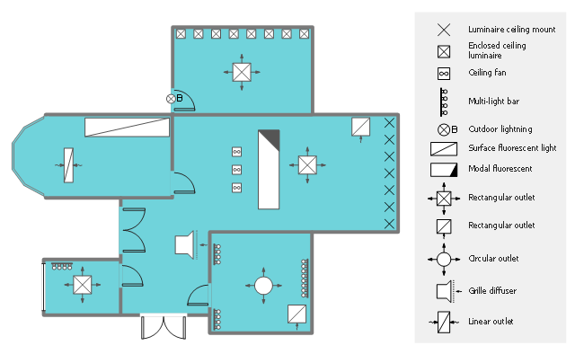
This reflected ceiling plan (RCP) sample shows lighting and HVAC layout.
"A "reflected ceiling plan" shows a view of the room as if looking from above, through the ceiling, at a mirror installed one foot below the ceiling level, which shows the reflected image of the ceiling above. This convention maintains the same orientation of the floor and ceilings plans - looking down from above. Reflected Ceiling Plans or RCP's are used by designers and architects to demonstrate lighting, visible mechanical features, and ceiling forms as part of the documents provided for construction." [Floor plan. Wikipedia]
The lighting and HVAC layout example "Reflected ceiling plan" was created using the ConceptDraw PRO diagramming and vector drawing software extended with the Reflected Ceiling Plans solution from the Building Plans area of ConceptDraw Solution Park.
Lighting and HVAC layout
Residential Electric Plan

- Lighting and switch layout | Design elements - Electrical and telecom
- Architectural Lighting Symbols
- Architectural Electrical Symbols
- Electrical Drawing Software | How To use House Electrical Plan ...
- Design elements - Lighting | Lighting and switch layout | Classroom ...
- Lighting Symbol
- Floor Plan Lighting Symbols
- Standard Electrical Lighting Symbols
- How To use House Electrical Plan Software | Electrical Drawing ...
- Electrical Diagram Symbols
- Design elements - Electrical and telecom | Design elements ...
- Lighting Layout Symbols
- Lighting and switch layout | Design elements - Lighting | Design ...
- Drawing Electrical Symbols
- Design elements - Electrical and telecom | Electrical Drawing ...
- Classroom lighting - Reflected ceiling plan | Design elements ...
- Architectural Symbols For Electrical Wiring
- Design elements - Electrical and telecom | Electrical Drawing ...
- Lighting Plan Symbols Sockets
- Electrical Engineering | How to Create an Electrical Diagram | CAD ...
- ERD | Entity Relationship Diagrams, ERD Software for Mac and Win
- Flowchart | Basic Flowchart Symbols and Meaning
- Flowchart | Flowchart Design - Symbols, Shapes, Stencils and Icons
- Flowchart | Flow Chart Symbols
- Electrical | Electrical Drawing - Wiring and Circuits Schematics
- Flowchart | Common Flowchart Symbols
- Flowchart | Common Flowchart Symbols