UML Class Diagram Generalization Example UML Diagrams

This sample describes the use of the classes, the generalization associations between them, the multiplicity of associations and constraints. Provided UML diagram is one of the examples set that are part of Rapid UML solution.
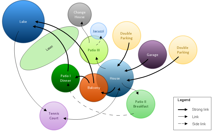
Bubble diagrams in Landscape Design with ConceptDraw DIAGRAM
Entity Relationship Diagram Symbols

ERD symbols used for professional ERD drawing are collected in libraries from the Entity-Relationship Diagram (ERD) solution for ConceptDraw DIAGRAM.
Data structure diagram with ConceptDraw DIAGRAM

HelpDesk
How to Draw a Block Diagram

Local area network (LAN). Computer and Network Examples
 diagram")
ConceptDraw - Perfect Network Diagramming Software with examples of LAN Diagrams. ConceptDraw Network Diagram is ideal for network engineers and network designers who need to draw Local Area Network diagrams.

Data Modeling with Entity Relationship Diagram

The best ERD tool for the Mac and Windows is ConceptDraw DIAGRAM software extended with the Entity-Relationship Diagram (ERD) solution from the Software Development Area for ConceptDraw Solution Park, which is sharpened for professional ERD drawing and data modeling with Entity Relationship Diagram.
Modelling Concepts for Business Engineering - EPC

ConceptDraw DIAGRAM - software that reduces the time needed to create a business process model.
 Block Diagrams
Block diagrams solution extends ConceptDraw DIAGRAM software with templates, samples and libraries of vector stencils for drawing the block diagrams.
UML Component Diagram Example - Online Shopping

This sample shows the concept of the online shopping and is used for the understanding of the online shopping processes, of the online shops working processes, for projection and creating of the online stores.
- Tool To Draw Conceptual Model
- Gambar Conceptual Diagram Of The Kanban System Toyota
- Uml Conceptual Model Of Online Shopping
- Conceptual Diagram Of Online Medical
- Conceptual Diagrams Example For Apartments
- Marketing | Competitor Analysis | Swot Analysis Examples | Concept ...
- Conceptual diagram of the Kanban System | Gambar Area Diagram
- Diagram Marketing Concept
- Conceptual diagram of the Kanban System | Fishbone Diagrams ...
- Conceptual diagram of the Kanban System | Business - Workflow ...
- ERD | Entity Relationship Diagrams, ERD Software for Mac and Win
- Flowchart | Basic Flowchart Symbols and Meaning
- Flowchart | Flowchart Design - Symbols, Shapes, Stencils and Icons
- Flowchart | Flow Chart Symbols
- Electrical | Electrical Drawing - Wiring and Circuits Schematics
- Flowchart | Common Flowchart Symbols
- Flowchart | Common Flowchart Symbols