The vector stencils library "Computers" contains 52 hardware icons.
Use it to design your audio, video and multimedia illustrations, presentations, web pages and infographics with ConceptDraw PRO diagramming and vector drawing software.
The vector stencils library "Computers" is included in the Audio, Video, Media solution from the Illustration area of ConceptDraw Solution Park.
Workstation

Desktop computer

Monitor with keyboard

PC

iMac

Mac computer

Monitor

Display screen

Computer monitor

LCD monitor 1

LCD monitor 2

LCD screen 1

LCD screen 2

Web design

MacBook

iBook

Laptop 1

Laptop 2

Laptop 3

Laptop 4

Notebook

Online video

Laptop settings

Webcam

Web camera 1

Web camera 2

Computer camera

Network server

Data center

Tower computer

Power Mac

Image scanner

Inkjet printer 1

Inkjet printer 2

Laser printer 1
Laser printer 2

Cable cord

USB cable
Online game
Portable gamepad

Game pad

Joystick 1

Joystick 2

Car drive

Glasses

3D glasses

Calculator
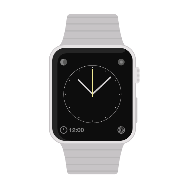
iWatch
Digital clock

Clock

Timer

Waiting

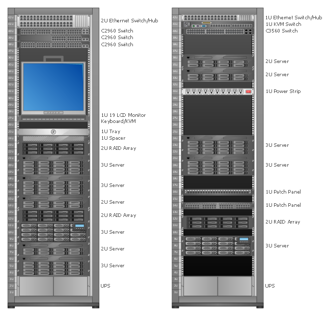
The vector stencils library "Rack diagrams" contains 33 rack design elements for drawing the computer network server rack diagrams.
"A 19-inch rack is a standardized frame or enclosure for mounting multiple equipment modules. Each module has a front panel that is 19 inches (482.6 mm) wide, including edges or ears that protrude on each side which allow the module to be fastened to the rack frame with screws. ...
Equipment designed to be placed in a rack is typically described as rack-mount, rack-mount instrument, a rack mounted system, a rack mount chassis, subrack, rack mountable, or occasionally simply shelf. The height of the electronic modules is also standardized as multiples of 1.75 inches (44.45 mm) or one rack unit or U (less commonly RU). The industry standard rack cabinet is 42U tall. ...
19-inch racks in 2-post or 4-post form hold most equipment in modern data centers, ISP facilities and professionally designed corporate server rooms. They allow for dense hardware configurations without occupying excessive floorspace or requiring shelving." [19-inch rack. Wikipedia]
The clip art example "Rack diagrams - Vector stencils library" was created using the ConceptDraw PRO diagramming and vector drawing software extended with the Rack Diagrams solution from the Computer and Networks area of ConceptDraw Solution Park.
19 inch Rack with Rails

Rack

Rack rails

Rack rails (half-width)
-rack-diagrams---vector-stencils-library.png--diagram-flowchart-example.png)
Single rack rail

Xserve RAID

XServe

1U tray

1U spacer

2U server

1U Ethernet Switch/Hub

2U Ethernet Switch/Hub

1U power strip

1U KVM switch

1U patch panel

Rackmount UPS

Cisco switch (WS-C3560-24PS-S)
-rack-diagrams---vector-stencils-library.png--diagram-flowchart-example.png)
Cisco switch (WS-C3560-48TS-S)
-rack-diagrams---vector-stencils-library.png--diagram-flowchart-example.png)
Cisco switch (WS-C2960-48TT-L)
-rack-diagrams---vector-stencils-library.png--diagram-flowchart-example.png)
Cisco switch (WS-C2960-48TC-L)
-rack-diagrams---vector-stencils-library.png--diagram-flowchart-example.png)
Cisco switch (WS-C2960-24TT-L)
-rack-diagrams---vector-stencils-library.png--diagram-flowchart-example.png)
Cisco switch (WS-C2960-24TC-L)
-rack-diagrams---vector-stencils-library.png--diagram-flowchart-example.png)
7U rackmount LCD monitor

8U rackmount LCD monitor

Fiber optic patch panel (type A)
-rack-diagrams---vector-stencils-library.png--diagram-flowchart-example.png)
Fiber optic patch panel (type B)
-rack-diagrams---vector-stencils-library.png--diagram-flowchart-example.png)
Fiber optic patch panel (type C)
-rack-diagrams---vector-stencils-library.png--diagram-flowchart-example.png)
3U server

2U RAID array

3U RAID array

Managed UPS

1U 19'' LCD monitor keyboard

1U server

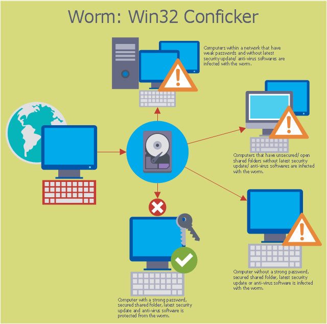
This computer security diagram example was designed on the base of the Wikimedia Commons file: Conficker.svg. [commons.wikimedia.org/ wiki/ File:Conficker.svg]
This file is licensed under the Creative Commons Attribution-Share Alike 3.0 Unported license. [creativecommons.org/ licenses/ by-sa/ 3.0/ deed.en]
"A computer worm is a standalone malware computer program that replicates itself in order to spread to other computers. Often, it uses a computer network to spread itself, relying on security failures on the target computer to access it. Unlike a computer virus, it does not need to attach itself to an existing program. Worms almost always cause at least some harm to the network, even if only by consuming bandwidth, whereas viruses almost always corrupt or modify files on a targeted computer." [Computer worm. Wikipedia]
The cybersecurity diagram example "Spread of Conficker worm" was created using the ConceprDraw PRO software extended with the Network Security Diagrams solution from the Computer and Neworks area of ConceptDraw Solution Park.
Computer security diagram
This telecom diagram sample illustrates the call shop solution. It was designed on the base of the Wikimedia Commons file: Call shops.jpg.
[commons.wikimedia.org/ wiki/ File:Call_ shops.jpg]
This file is licensed under the Creative Commons Attribution-Share Alike 3.0 Unported license. [creativecommons.org/ licenses/ by-sa/ 3.0/ deed.en]
"A call shop is a business providing on-site access to telephones for long-distance calling in countries without widespread home long-distance service. Calls may be prepaid or postpaid." [Call shop. Wikipedia]
The telecommunication diagram example "Call shop solution" was created using the ConceptDraw PRO diagramming and vector drawing software extended with the Computers and Communications solution from the Illustration area of ConceptDraw Solution Park.
Telecom diagram

HelpDesk
How to Perform a Presentation on Mac Using Two Monitors

Network Security Devices

A five level pyramid model of different types of Information Systems based on the information processing requirement of different levels in the organization. The first level represents transaction processing systems to process basic data. The second level represents office support systems to process information in office. The third level represents management information systems to process information by managers. The fourth level represents decision support systems to process explicit knowledge. The fifth level represents executive information systems to process tacit knowledge.
"A Computer(-Based) Information System is essentially an IS using computer technology to carry out some or all of its planned tasks. The basic components of computer based information system are:
(1) Hardware - these are the devices like the monitor, processor, printer and keyboard, all of which work together to accept, process, show data and information.
(2) Software - are the programs that allow the hardware to process the data.
(3) Databases - are the gathering of associated files or tables containing related data.
(4) Networks - are a connecting system that allows diverse computers to distribute resources.
(5) Procedures - are the commands for combining the components above to process information and produce the preferred output.
The first four components (hardware, software, database and network) make up what is known as the information technology platform. Information technology workers could then use these components to create information systems that watch over safety measures, risk and the management of data. These actions are known as information technology services." [Information systems. Wikipedia]
This pyramid diagram was redesigned using the ConceptDraw PRO diagramming and vector drawing software from Wikimedia Commons file Five-Level-Pyramid-model.png. [commons.wikimedia.org/ wiki/ File:Five-Level-Pyramid-model.png]
This file is licensed under the Creative Commons Attribution 3.0 Unported license. [creativecommons.org/ licenses/ by/ 3.0/ deed.en]
The triangle chart example "Information systems types" is included in the Pyramid Diagrams solution from the Marketing area of ConceptDraw Solution Park.
Pyramid diagram

Rack Diagrams visualize the rack mounting of computer hardware and network equipment as the drawing of frontal view of the rack with equipment installed.
They are used for choosing the equipment or racks to buy, and help to organize equipment on the racks virtually, without the real installation.
"A server is a system (software and suitable computer hardware) that responds to requests across a computer network to provide, or help to provide, a network service. Servers can be run on a dedicated computer, which is also often referred to as "the server", but many networked computers are capable of hosting servers. In many cases, a computer can provide several services and have several servers running. ...
Servers often provide essential services across a network, either to private users inside a large organization or to public users via the Internet. Typical computing servers are database server, file server, mail server, print server, web server, gaming server, application server..." [Server (computing). Wikipedia]
This network server rack diagram example was created using the ConceptDraw PRO diagramming and vector drawing software extended with the Rack Diagrams solution from the Computer and Networks area of ConceptDraw Solution Park.
Rack diagram
Construction Project Chart Examples
This pinout diagram example showing a VGA connector (as viewed from the socket) was redesigned from the Wikimedia Commons file: DE15 Connector Pinout.svg. [commons.wikimedia.org/ wiki/ File:DE15_ Connector_ Pinout.svg]
"A Video Graphics Array (VGA) connector is a three-row 15-pin DE-15 connector. The 15-pin VGA connector is found on many video cards, computer monitors, and high definition television sets. On laptop computers or other small devices, a mini-VGA port is sometimes used in place of the full-sized VGA connector.
DE-15 is also conventionally called RGB connector, D-sub 15, mini sub D15, mini D15, DB-15, HDB-15, HD-15 or HD15 (High Density, to distinguish it from the older and less flexible DE-9 connector used on some older VGA cards, which has the same shell size but only two rows of pins).
VGA connectors and cables carry analog component RGBHV (red, green, blue, horizontal sync, vertical sync) video signals, and VESA Display Data Channel (VESA DDC) data. In the original version of DE-15 pinout, one pin was keyed by plugging the female connector hole; this prevented non-VGA 15 pin cables from being plugged into a VGA socket. Four pins carried Monitor ID bits which were rarely used; VESA DDC redefined some of these pins and replaced the key pin with +5 V DC power supply.
The VGA interface is not engineered to be hotpluggable (so that the user can connect or disconnect the output device while the host is running), although in practice this can be done and usually does not cause damage to the hardware or other problems. However, nothing in the design ensures that the ground pins make a connection first and break last, so hotplugging may introduce surges in signal lines which may or may not be adequately protected against. Also, depending on the hardware and software, detecting a monitor being connected might not work properly in all cases." [VGA connector. Wikipedia]
The pinout diagram example "VGA connector pinout" was created using the ConceptDraw PRO diagramming and vector drawing software extended with the Audio and Video Connectors solution from the Engineering area of ConceptDraw Solution Park.
VGA connector pinout

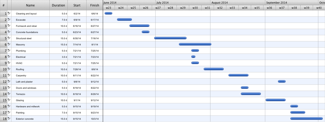
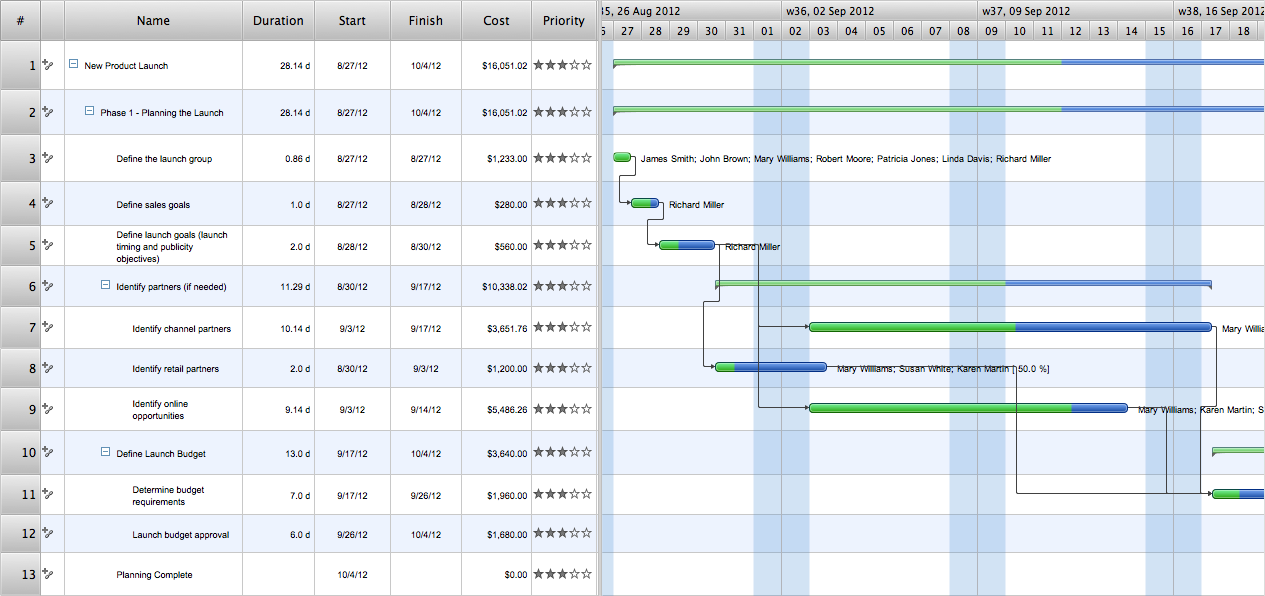
Gantt Chart Software
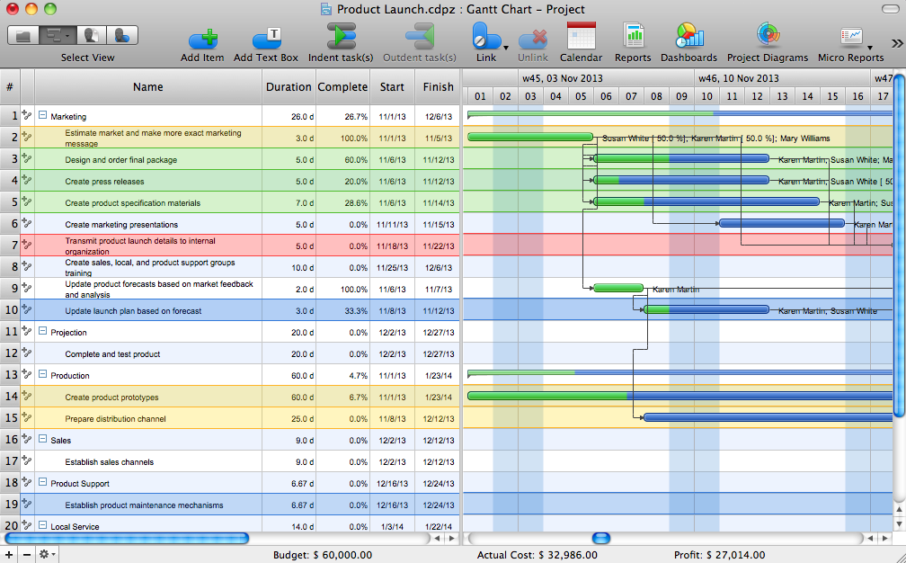
How To Plan and Implement Projects Faster
Interior Design. Office Layout Plan Design Element

ConceptDraw Building Drawing Tools - draw simple office layout plans easily with Office Layout Plan Design Element. Use it to draw office interior design floor plans, office furniture and equipment layouts, and blueprints for facilities management, move management, office supply inventories, assets inventories, office space planning.

HelpDesk
How To Create the Interaction (Relations) Diagram
 Diagram")
- Server rack diagram | Computers - Vector stencils library | Interior ...
- Remote Computer Monitor System Case Tool Activity Diagram
- Home area networks (HAN). Computer and Network Examples ...
- Computers - Vector stencils library
- Computers - Vector stencils library | Hardware - Vector stencils ...
- Design elements - Computers | How To Create CCTV Network ...
- Mobile satellite TV network diagram | Building Networks | Computers ...
- Local area network (LAN). Computer and Network Examples ...
- Camera layout schematic | Marketing Diagrams | Computers and ...
- Diagrams Of Computer Monitor
- Rack Diagrams
- Diagram Of Firewall Computer
- Diamgram For Computer Monitor
- Computers - Vector stencils library | Computer network - Vector ...
- Computer Security Program
- ConceptDraw PRO Network Diagram Tool | Audio and Video ...
- Call shop solution | Network diagrams with ConceptDraw PRO ...
- Remote Computer Monitoring System Class Diagram
- Server Computer Diagram
- Computers and network isometric - Vector stencils library | Rack ...
- ERD | Entity Relationship Diagrams, ERD Software for Mac and Win
- Flowchart | Basic Flowchart Symbols and Meaning
- Flowchart | Flowchart Design - Symbols, Shapes, Stencils and Icons
- Flowchart | Flow Chart Symbols
- Electrical | Electrical Drawing - Wiring and Circuits Schematics
- Flowchart | Common Flowchart Symbols
- Flowchart | Common Flowchart Symbols