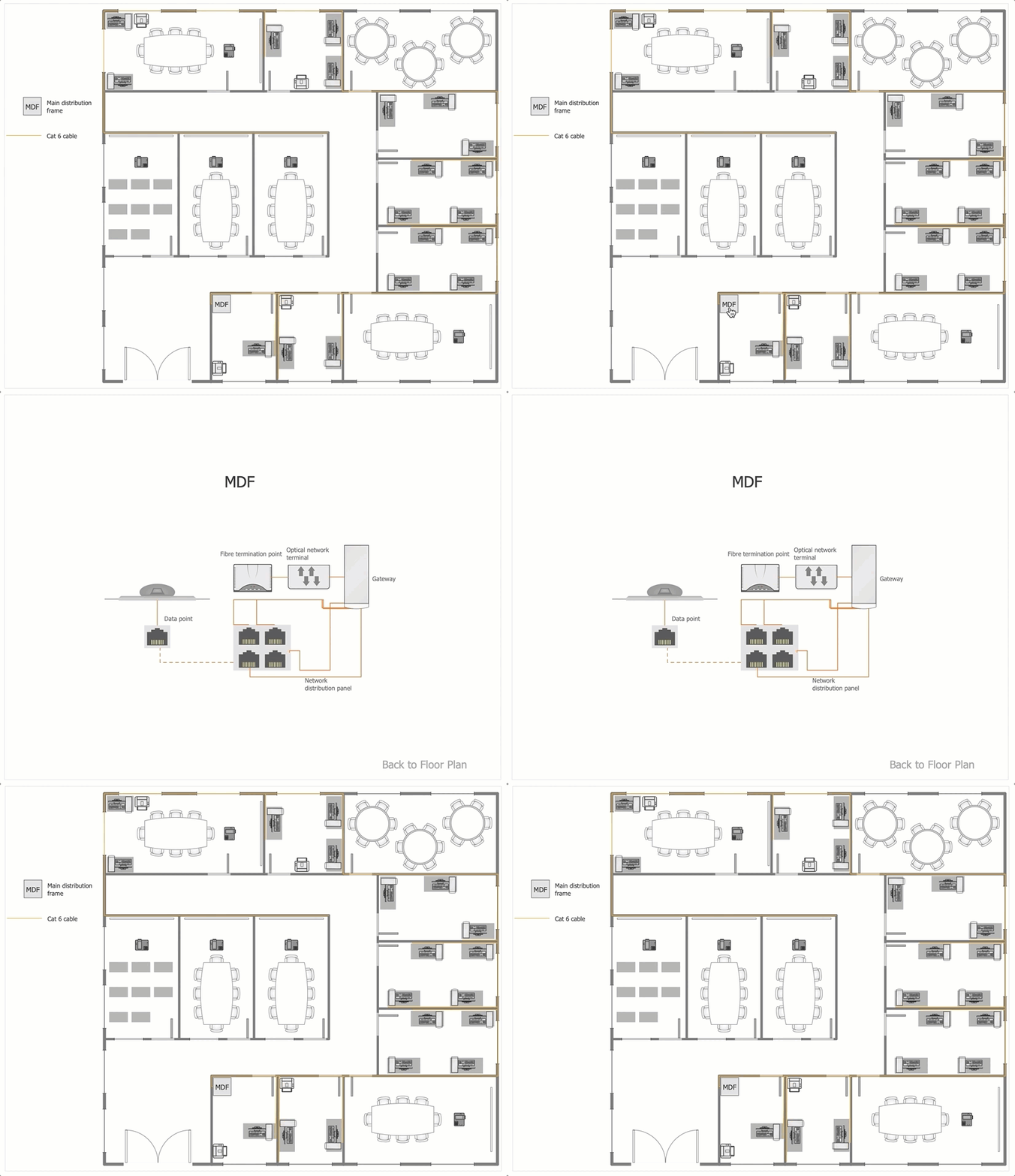
 Network Layout Floor Plans
Network Layout Floor Plans solution extends ConceptDraw DIAGRAM software functionality with powerful tools for quick and efficient documentation the network equipment and displaying its location on the professionally designed Network Layout Floor Plans. Never before creation of Network Layout Floor Plans, Network Communication Plans, Network Topologies Plans and Network Topology Maps was not so easy, convenient and fast as with predesigned templates, samples, examples and comprehensive set of vector design elements included to the Network Layout Floor Plans solution. All listed types of plans will be a good support for the future correct cabling and installation of network equipment.
Network Layout
ConceptDraw has 1004 vector stencils in the 40 libraries that helps you to start using software for designing your own Network Layout Diagrams. You can use the appropriate stencils from Computer and Network Diagrams object libraries.
This reflected ceiling plan example shows the lighting scheme of computer lab with overhead projector. It was drawn on the base of the RCP from website of Elon University, Elon, NC.
[elon.edu/ docs/ e-web/ bft/ cmdept/ Reflected%20 Ceiling.JPG]
"An overhead projector is a variant of slide projector that is used to display images to an audience. ...
Use in education.
The overhead projector facilitates an easy low-cost interactive environment for educators. Teaching materials can be pre-printed on plastic sheets, upon which the educator can directly write using a non-permanent, washable color marking pen. This saves time, since the transparency can be pre-printed and used repetitively, rather than having materials written manually before each class.
The overhead is typically placed at a comfortable writing height for the educator and allows the educator to face the class, facilitating better communication between the students and teacher. The enlarging features of the projector allow the educator to write in a comfortable small script in a natural writing position rather than writing in an overly large script on a blackboard and having to constantly hold his arm out in midair to write on the blackboard.
When the transparency sheet is full of written or drawn material, it can simply be replaced with a new, fresh sheet with more pre-printed material, again saving class time vs a blackboard that would need to be erased and teaching materials rewritten by the educator. Following the class period, the transparencies are easily restored to their original unused state by washing off with soap and water." [Overhead projector. Wikipedia]
The classroom reflected ceiling plan example "Computer lab RCP" was created using the ConceptDraw DIAGRAM diagramming and vector drawing software extended with the Reflected Ceiling Plans solution from the Building Plans area of ConceptDraw Solution Park.
Computer Network Architecture. Computer and Network Examples
The network architecture and design specialization will help you gain the technical leadership skills you need to design and implement high-quality networks that support business needs.
 Computer Network Diagrams
Computer Network Diagrams solution extends ConceptDraw DIAGRAM software with samples, templates and libraries of vector icons and objects of computer network devices and network components to help you create professional-looking Computer Network Diagrams, to plan simple home networks and complex computer network configurations for large buildings, to represent their schemes in a comprehensible graphical view, to document computer networks configurations, to depict the interactions between network's components, the used protocols and topologies, to represent physical and logical network structures, to compare visually different topologies and to depict their combinations, to represent in details the network structure with help of schemes, to study and analyze the network configurations, to communicate effectively to engineers, stakeholders and end-users, to track network working and troubleshoot, if necessary.
HelpDesk
How to Create a Network Layout Floor Plan
With technology and market forces demanding ever quicker business response times, a well-structured computer network is the foundation of positive communication between employees, and with the wider world. When you walk into most modern work offices, there is a good chance you will be greeted by banks of computer screens and terminals, perhaps some sales points screens or server stacks, almost certainly routers and printers. A side effect of this amount of hardware is the amount of cabling necessary to connect these elements into an effective local area network (LAN). This is the idea behind a network layout plan - it can show how a network is connected, how data transfers between those connections, and give an overview of devices and hardware used in the office. To create a practical computer network floor plan, the network administrator must adhere to the specified requirements and limitations of the office or building in which the LAN will operate - things such as hardware availability,- Network Layout Floor Plans | Computer Network Architecture ...
- Floor Plan With Computer Networks
- Network Layout Floor Plans | Local area network (LAN). Computer ...
- Floor Plan In Computer Institute Wit Office
- How To Draw A Floor Plan For A Computer Centre
- Network Layout Floor Plans | Campus Area Networks (CAN ...
- Floor Plan For Computer Networking
- Network Layout Floor Plans | Network Visualization | Local area ...
- Network Layout Floor Plans | Network Layout | Local area network ...
- Network wiring cable. Computer and Network Examples | Network ...
- ERD | Entity Relationship Diagrams, ERD Software for Mac and Win
- Flowchart | Basic Flowchart Symbols and Meaning
- Flowchart | Flowchart Design - Symbols, Shapes, Stencils and Icons
- Flowchart | Flow Chart Symbols
- Electrical | Electrical Drawing - Wiring and Circuits Schematics
- Flowchart | Common Flowchart Symbols
- Flowchart | Common Flowchart Symbols


