UML Deployment Diagram. Design Elements

ConceptDraw has 393 vector stencils in the 13 libraries that helps you to start using software for designing your own UML Diagrams. You can use the appropriate stencils of UML notation from UML Deployment library.
UML Tool & UML Diagram Examples

Solution RapidUML from Software Development area of ConceptDraw Solution Park provides templates, examples and 13 vector stencils libraries for drawing all types of UML 1.x and 2.x diagrams using ConceptDraw DIAGRAM diagramming and vector drawing software.
Use these UML diagram templates and examples to quickly start drawing your own UML diagrams.
UML in 10 mins

This sample describes the credit card processing system. It’s a UML Class Diagram with generalization sets. This sample can be used by the banks, business and financial companies, exchanges.
UML Class Diagram Example - Apartment Plan

This sample show the detailed plan of the apartment and is used by building companies, design apartments, real estate agencies, at the buying / selling of the realty.
Process Flowchart


Financial Trade UML Use Case Diagram Example

This sample shows the work of the Financial Trade sphere and can be used by trading companies, commercial organizations, traders, different exchanges.
UML Class Diagram Example - Social Networking Site
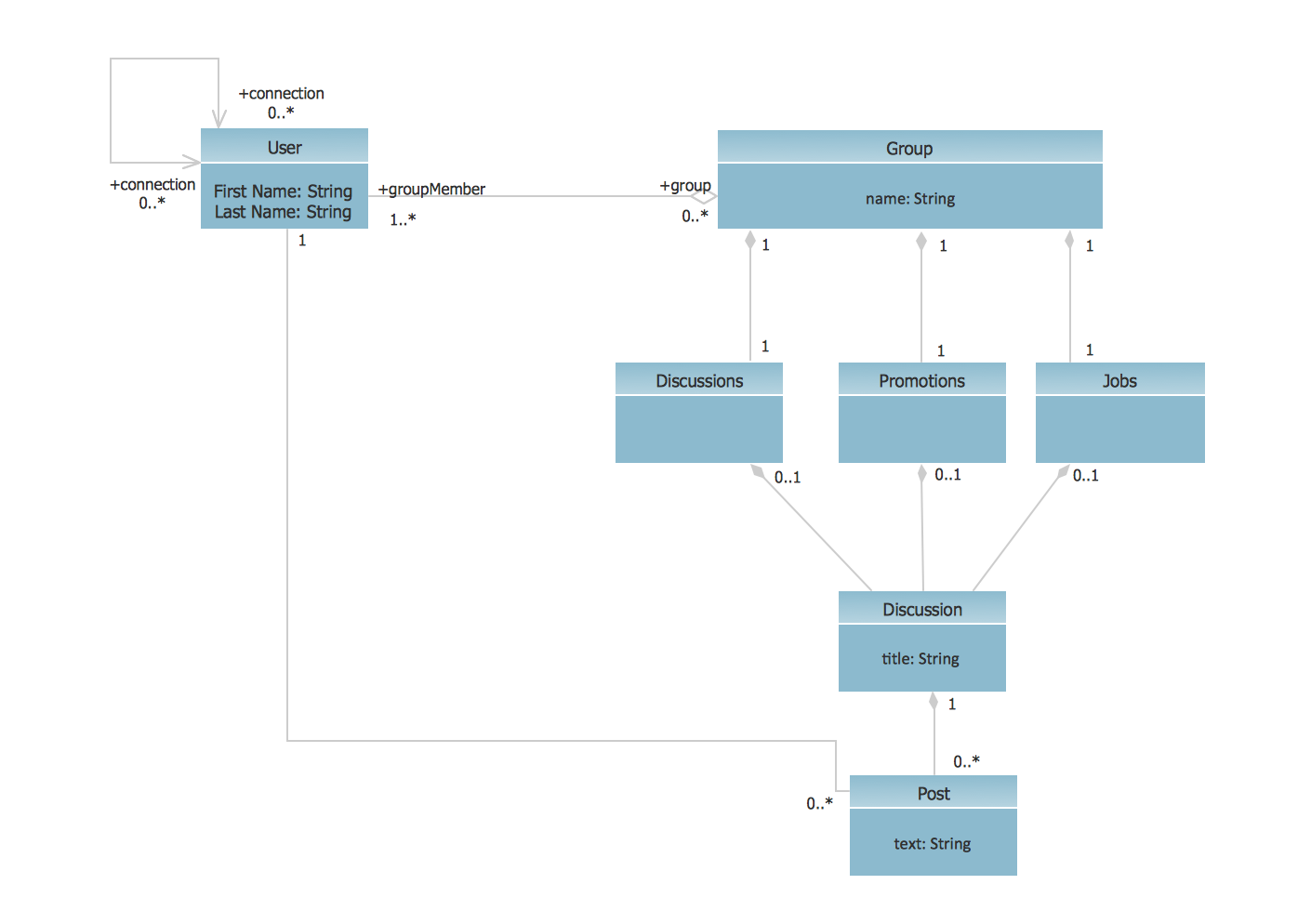
This sample shows the structure of the popular social networking site Linkedin and is used in the business field, in IT, at the projection and creating of the social networking sites.
Entity Relationship Diagram Examples

ConceptDraw gives the ability to describe a database using the Entity-Relationship model. Entity-Relationship Diagram solution includes icons advocated by Chen's and Crow’s Foot notation that can be used when describing a database.

 AWS Architecture Diagrams
AWS Architecture Diagrams with powerful drawing tools and numerous predesigned Amazon icons and AWS simple icons is the best for creation the AWS Architecture Diagrams, describing the use of Amazon Web Services or Amazon Cloud Services, their application for development and implementation the systems running on the AWS infrastructure. The multifarious samples give you the good understanding of AWS platform, its structure, services, resources and features, wide opportunities, advantages and benefits from their use; solution’s templates are essential and helpful when designing, description and implementing the AWS infrastructure-based systems. Use them in technical documentation, advertising and marketing materials, in specifications, presentation slides, whitepapers, datasheets, posters, etc.
Diagramming Software for Design UML Activity Diagrams


- UML Deployment Diagram Example - ATM System UML diagrams ...
- UML Use Case Diagram Example Social Networking Sites Project ...
- System Flowcharts Of A Room Renting System
- Hotel reservation system | Manual Booking System
- Sales Flowcharts | Hotel reservation system | Cross-functional ...
- Erd For Car Rental System
- Hotel reservation system | Sales Flowcharts | Manual Reservation ...
- Invoice payment process - Flowchart | UML component diagram ...
- Context Diagram Template | DFD Library System | Example of DFD ...
- Swim Lane Diagrams | Swim Lane Flowchart Symbols | Cross ...
- ERD | Entity Relationship Diagrams, ERD Software for Mac and Win
- Flowchart | Basic Flowchart Symbols and Meaning
- Flowchart | Flowchart Design - Symbols, Shapes, Stencils and Icons
- Flowchart | Flow Chart Symbols
- Electrical | Electrical Drawing - Wiring and Circuits Schematics
- Flowchart | Common Flowchart Symbols
- Flowchart | Common Flowchart Symbols