"A computer network or data network is a telecommunications network that allows computers to exchange data. In computer networks, networked computing devices (network nodes) pass data to each other along data connections. The connections (network links) between nodes are established using either cable media or wireless media. The best-known computer network is the Internet.
Network devices that originate, route and terminate the data are called network nodes. Nodes can include hosts such as servers and personal computers, as well as networking hardware. Two devices are said to be networked when a device is able to exchange information with another device." [Computer network. Wikipedia]
This computer communication network diagram example was created using the ConceptDraw PRO diagramming and vector drawing software extended with the Computer and Networks solution from the Computer and Networks area of ConceptDraw Solution Park.
Network diagram

 Telecommunication Network Diagrams
Telecommunication Network Diagrams solution extends ConceptDraw PRO software with samples, templates, and great collection of vector stencils to help the specialists in a field of networks and telecommunications, as well as other users to create Computer systems networking and Telecommunication network diagrams for various fields, to organize the work of call centers, to design the GPRS networks and GPS navigational systems, mobile, satellite and hybrid communication networks, to construct the mobile TV networks and wireless broadband networks.
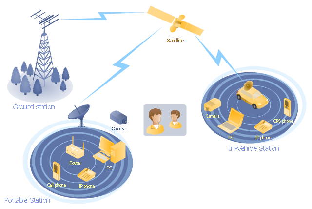
"Mobile satellite systems help connect remote regions, vehicles, ships, people and aircraft to other parts of the world and/ or other mobile or stationary communications units, in addition to serving as navigation systems." [Satellite. Mobile satellite systems. Wikipedia]
"A communications satellite or comsat is an artificial satellite sent to space for the purpose of telecommunications.
... communications satellites ... are ... used for mobile applications such as communications to ships, vehicles, planes and hand-held terminals, and for TV and radio broadcasting." [Communications satellite. Wikipedia]
This mobile satellite communication network diagram was created using the ConceptDraw PRO diagramming and vector drawing software extended with the Telecommunication Network Diagrams solution from the Computer and Networks area of ConceptDraw Solution Park.
Mobile satellite network diagram
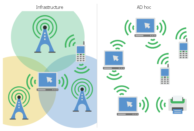
This infographic sample visualizes the Conventional and wireless ad hoc network. It was designed on the base of the Wikimedia Commons file: Běžná bezdrátová síť a ad hoc síť.png.
[commons.wikimedia.org/ wiki/ File:B%C4%9B%C5%BEn%C3%A1_ bezdr%C3%A1tov%C3%A1_ s%C3%AD%C5%A5_ a_ ad_ hoc_ s%C3%AD%C5%A5.png]
This file is licensed under the Creative Commons Attribution-Share Alike 4.0 International license. [creativecommons.org/ licenses/ by-sa/ 4.0/ deed.en]
"A wireless ad hoc network (WANET) is a decentralized type of wireless network. The network is ad hoc because it does not rely on a pre existing infrastructure, such as routers in wired networks or access points in managed (infrastructure) wireless networks. Instead, each node participates in routing by forwarding data for other nodes, so the determination of which nodes forward data is made dynamically on the basis of network connectivity. In addition to the classic routing, ad hoc networks can use flooding for forwarding data.
Wireless mobile ad hoc networks are self-configuring, dynamic networks in which nodes are free to move. Wireless networks lack the complexities of infrastructure setup and administration, enabling devices to create and join networks "on the fly" – anywhere, anytime." [Wireless ad hoc network. Wikipedia]
The infographic example "Conventional and wireless ad hoc network" was created using the ConceptDraw PRO diagramming and vector drawing software extended with the Computers and Communications solution from the Illustration area of ConceptDraw Solution Park.
Network infographic
"Media (singular medium) are the storage and transmission channels or tools used to store and deliver information or data. It is often referred to as synonymous with mass media or news media, but may refer to any means of information communication. ...
Analog telecommunications include some radio systems, historical telephony systems, and historical TV broadcasts.
Digital telecommunications allow for computer-mediated communication, telegraphy, and computer networks.
Modern communication media now allow for intense long-distance exchanges between larger numbers of people (many-to-many communication via e-mail, Internet forums, and teleportation). On the other hand, many traditional broadcast media and mass media favor one-to-many communication (television, cinema, radio, newspaper, magazines, and also facebook)." [Media (communication). Wikipedia]
This communication medium diagram example was created using the ConceptDraw PRO diagramming and vector drawing software extended with the Telecommunication Network Diagrams solution from the Computer and Networks area of ConceptDraw Solution Park.
Telecommunication network diagram

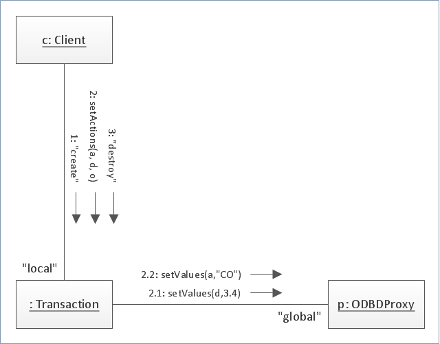
"Communication diagram (called collaboration diagram in UML 1.x) is a kind of UML interaction diagram which shows interactions between objects and/ or parts (represented as lifelines) using sequenced messages in a free-form arrangement.
Communication diagram corresponds (i.e. could be converted to/ from or replaced by) to a simple sequence diagram without structuring mechanisms such as interaction uses and combined fragments. It is also assumed that message overtaking (i.e., the order of the receptions are different from the order of sending of a given set of messages) will not take place or is irrelevant." [uml-diagrams.org/ communication-diagrams.html]
The template "UML communication diagram" for the ConceptDraw PRO diagramming and vector drawing software is included in the Rapid UML solution from the Software Development area of ConceptDraw Solution Park.
www.conceptdraw.com/ solution-park/ software-uml
UML communication diagram
 Computer Network Diagrams
Computer Network Diagrams solution extends ConceptDraw PRO software with samples, templates and libraries of vector icons and objects of computer network devices and network components to help you create professional-looking Computer Network Diagrams, to plan simple home networks and complex computer network configurations for large buildings, to represent their schemes in a comprehensible graphical view, to document computer networks configurations, to depict the interactions between network's components, the used protocols and topologies, to represent physical and logical network structures, to compare visually different topologies and to depict their combinations, to represent in details the network structure with help of schemes, to study and analyze the network configurations, to communicate effectively to engineers, stakeholders and end-users, to track network working and troubleshoot, if necessary.
 Entity-Relationship Diagram (ERD)
Entity-Relationship Diagram (ERD) solution extends ConceptDraw PRO software with templates, samples and libraries of vector stencils from drawing the ER-diagrams by Chen's and crow’s foot notations.
 Computers and Communications
Computers and communications solution extends ConceptDraw PRO software with illustration samples, templates and vector stencils libraries with clip art of computers, control devices, communications, technology, Apple machines.
Network Diagram Software Backbone Network


 Fishbone Diagram
Fishbone Diagrams solution extends ConceptDraw PRO software with templates, samples and library of vector stencils for drawing the Ishikawa diagrams for cause and effect analysis.
"The client–server model of computing is a distributed application structure that partitions tasks or workloads between the providers of a resource or service, called servers, and service requesters, called clients. Often clients and servers communicate over a computer network on separate hardware, but both client and server may reside in the same system. A server host runs one or more server programs which share their resources with clients. A client does not share any of its resources, but requests a server's content or service function. Clients therefore initiate communication sessions with servers which await incoming requests.
Examples of computer applications that use the client–server model are Email, network printing, and the World Wide Web." [Client–server model. Wikipedia]
The UML communication diagram example "Client server access" was created using the ConceptDraw PRO diagramming and vector drawing software extended with the Rapid UML solution from the Software Development area of ConceptDraw Solution Park.
UML communication diagram

 Network Layout Floor Plans
Network Layout Floor Plans solution extends ConceptDraw PRO software functionality with powerful tools for quick and efficient documentation the network equipment and displaying its location on the professionally designed Network Layout Floor Plans. Never before creation of Network Layout Floor Plans, Network Communication Plans, Network Topologies Plans and Network Topology Maps was not so easy, convenient and fast as with predesigned templates, samples, examples and comprehensive set of vector design elements included to the Network Layout Floor Plans solution. All listed types of plans will be a good support for the future correct cabling and installation of network equipment.
- Communication network diagram | Computers and Communications ...
- Mobile satellite communication network diagram | Hybrid satellite ...
- Communication network diagram
- Communication network diagram | Mobile satellite communication ...
- Communication network diagram | Mobile satellite communication ...
- Communication Diagram UML2.0 / Collaboration UML1.x ...
- Diagramming Software for Design UML Communication Diagrams ...
- Mobile satellite communication network diagram | Using Both Wired ...
- Mobile satellite communication network diagram | Satellite network ...
- Communication Diagram UML2.0 / Collaboration UML1.x ...
- Network Diagram Examples
- Communication network diagram | Concept maps with ConceptDraw ...
- Using Both Wired and Wireless Connections | Wireless access point ...
- Idea Communication | Diagramming Software for Design UML ...
- Example of DFD for Online Store (Data Flow Diagram ) DFD ...
- Mobile satellite communication network diagram | Network ...
- UML Collaboration Diagram Example Illustration | Diagramming ...
- Communication network diagram | Universal Diagramming Area ...
- GPS operation diagram | Local area network (LAN) diargam ...
- Communication network diagram | Logical network diagram ...
- ERD | Entity Relationship Diagrams, ERD Software for Mac and Win
- Flowchart | Basic Flowchart Symbols and Meaning
- Flowchart | Flowchart Design - Symbols, Shapes, Stencils and Icons
- Flowchart | Flow Chart Symbols
- Electrical | Electrical Drawing - Wiring and Circuits Schematics
- Flowchart | Common Flowchart Symbols
- Flowchart | Common Flowchart Symbols