HelpDesk
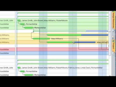
What Information to be Displayed in the ConceptDraw PROJECT Gantt Chart View

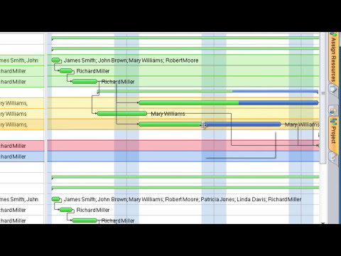
Managing the task list

HelpDesk
What Information can be Displayed in the Multiproject Dashboard View

Gant Chart in Project Management

Gantt charts for planning and scheduling projects

Cross-Functional Flowchart

Use cross-functional flowcharts to show the relationship between a business process and the functional units (such as departments) responsible for that process. To create it use the best flowchart maker of ConceptDraw PRO.

HelpDesk
How to Import Project Data From MS Excel File

HelpDesk
How to Determine what Information to be Displayed in the Project Resource List

HelpDesk
ConceptDraw PROJECT: Filter Tasks and Resources on Mac

HelpDesk
How to Customize the Columns in Your Project File

HelpDesk
How to Create a Custom Filter in ConceptDraw PROJECT for Windows

HelpDesk
How to Set a Project Baseline Using ConceptDraw PROJECT

 Status Dashboard
Status dashboard solution extends ConceptDraw PRO software with templates, samples and vector stencils libraries with graphic indicators for drawing the visual dashboards showing status data.
SIPOC Diagram

You need to draw professional looking SIPOC Diagram quick and easy? Pay please your attention on ConceptDraw PRO diagramming and vector drawing software. Extended with Business Process Mapping Solution from the Business Processes Area of ConceptDraw Solution Park, it suits ideal for this.
ERD Symbols and Meanings

The Chen's ERD notation is still used and is considered to present a more detailed way of representing entities and relationships.
To create an ERD, software engineers mainly turn to dedicated drawing software, which contain the full notation resources for their specific database design - ERD symbols and meanings. CS Odessa has released an all-inclusive Entity-Relationship Diagram (ERD) solution for their powerful drawing program, ConceptDraw PRO.

- Columns That Indicate The Tasks People And Dates Involved In A
- Gantt Chart For Computer Network Project
- Gant Chart in Project Management | Gantt chart examples | How to ...
- Project — Task Trees and Dependencies | Project — Working With ...
- How to Report Task's Execution with Gantt Chart | How to Create ...
- Gantt Chart Software | Project — Working With Costs | Product ...
- How to Track Your Project Plan vs. the Actual Project Condition ...
- Gantt chart examples | Gant Chart in Project Management | Gantt ...
- How to Track Your Project Plan vs. the Actual Project Condition ...
- Gantt chart examples | How to Customize the Columns in Your ...
- Examples Of Project Work
- How to Create a Gantt Chart for Your Project | Gantt Chart Software ...
- How to Determine what Information to be Displayed in the Project ...
- How to Draw a Gantt Chart Using ConceptDraw PRO | How to ...
- Project — Working With Tasks | How to Customize a Task's Duration ...
- What Information to be Displayed in the ConceptDraw PROJECT ...
- How to Make a Project Tasks Mind Map from Brainstorm | How to ...
- How to Report Task's Execution with Gantt Chart | How to Create ...
- Scrum sprint cycle | Scrum board suggesting to use Kanban | Scrum ...
- How to Change the Working Time in a Project | Time - Vector ...
- ERD | Entity Relationship Diagrams, ERD Software for Mac and Win
- Flowchart | Basic Flowchart Symbols and Meaning
- Flowchart | Flowchart Design - Symbols, Shapes, Stencils and Icons
- Flowchart | Flow Chart Symbols
- Electrical | Electrical Drawing - Wiring and Circuits Schematics
- Flowchart | Common Flowchart Symbols
- Flowchart | Common Flowchart Symbols