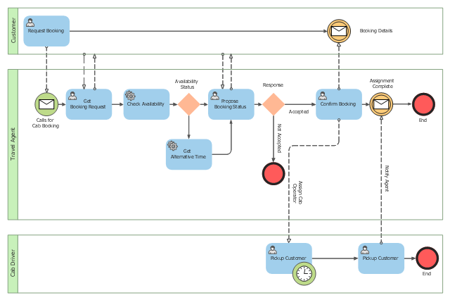
This BPMN (Business Process Model and Notation) collaboration diagram sample depicts interactions between customer, travel agent and cab driver, which are defined as a sequence of activities, and represent the message exchange during a cab booking process.
"Business process modeling is used to communicate a wide variety of information to a wide variety of audiences. BPMN is designed to cover this wide range of usage and allows modeling of end-to-end business processes to allow the viewer of the Diagram to be able to easily differentiate between sections of a BPMN Diagram. There are three basic types of sub-models within an end-to-end BPMN model: Private (internal) business processes, Abstract (public) processes, and Collaboration (global) processes...
Collaboration (global) processes.
A collaboration process depicts the interactions between two or more business entities. These interactions are defined as a sequence of activities that represent the message exchange patterns between the entities involved. Collaboration processes may be contained within a Pool and the different participant business interactions are shown as Lanes within the Pool. In this situation, each Lane would represent two participants and a direction of travel between them. They may also be shown as two or more Abstract Processes interacting through Message Flow. These processes can be modeled separately or within a larger BPMN Diagram to show the Associations between the collaboration process activities and other entities. If the collaboration process is in the same Diagram as one of its corresponding private business process, then the activities that are common to both processes can be associated." [Business Process Model and Notation. Wikipedia]
The business process modeling diagram example "Cab booking public process - Collaboration BPMN 2.0 diagram" was designed using the ConceptDraw PRO diagramming and vector drawing software extended with the Business Process Diagram solution from the Business Processes area of ConceptDraw Solution Park.
Business process modeling
Communication Diagram UML2.0 / Collaboration UML1.x


UML Diagrams with ConceptDraw DIAGRAM

ConceptDraw DIAGRAM is a software that provides possibility of detailed UML diagrams. A large number of stencils that coresponds to UML diagram notation and task-oriented templates.
How To Create a Workflow Diagram

The fastest way to create a workflow diagram is using pre-designed workflow template. ConceptDraw DIAGRAM with the Workflow Diagrams solution delivers rich set of workflow diagram templates you may start from.
"A communication diagram in the Unified Modeling Language (UML) 2.0, is a simplified version of the UML 1.x collaboration diagram. ...
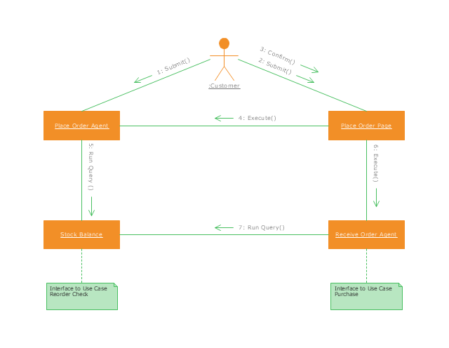
A Communication diagram models the interactions between objects or parts in terms of sequenced messages. Communication diagrams represent a combination of information taken from Class, Sequence, and Use Case Diagrams describing both the static structure and dynamic behavior of a system.
However, communication diagrams use the free-form arrangement of objects and links as used in Object diagrams. In order to maintain the ordering of messages in such a free-form diagram, messages are labeled with a chronological number and placed near the link the message is sent over. Reading a communication diagram involves starting at message 1.0, and following the messages from object to object.
Communication diagrams show a lot of the same information as sequence diagrams, but because of how the information is presented, some of it is easier to find in one diagram than the other.
Communication diagrams show which elements each one interacts with better, but sequence diagrams show the order in which the interactions take place more clearly." [Communication diagram. Wikipedia]
This UML communication diagram example was created using the ConceptDraw PRO diagramming and vector drawing software extended with the Rapid UML solution from the Software Development area of ConceptDraw Solution Park.
UML communication diagram
UML Activity Diagram

Use ConceptDraw DIAGRAM diagramming and vector drawing software enhanced with Rapid UML solution from ConceptDraw Solution Park to create your own UML activity diagrams that show the business and operational workflows of components and overall flow of control in your systems. Such software provides coloring UML diagrams for various purposes and simplifying work of the engineers.
UML Class Diagram Tutorial

Graphical Symbols to use in EPC diagrams

ConceptDraw DIAGRAM - software that reduces the time needed to create a business process model.
UML Class Diagram Generalization Example UML Diagrams

This sample describes the use of the classes, the generalization associations between them, the multiplicity of associations and constraints. Provided UML diagram is one of the examples set that are part of Rapid UML solution.
Workflow Diagram Software Mac

Use the ConceptDraw DIAGRAM professional Mac OS X software for drawing workflow diagram. The Workflow Diagrams solution with its libraries and templates set make the possibility to identify resources that are required for work goal implementation. The process flow diagram identify flow which occurs as network of process dependencies, organizational decisions and interactions between departments. Usually workflow diagrams show business participants actions that carry product or service to the final destination, the consumer.
Diagramming Software for Design UML Interaction Overview Diagrams

UML Object Diagram. Design Elements

ConceptDraw has 393 vector stencils in the 13 libraries that helps you to start using software for designing your own UML Diagrams. You can use the appropriate stencils of UML notation from UML Object library.
UML Timing Diagram, Design Elements

ConceptDraw has 393 vector stencils in the 13 libraries that helps you to start using software for designing your own UML Diagrams. You can use the appropriate stencils of UML notation from UML Timing library.
The Best Business Process Modeling Software

ConceptDraw has 142 vector stencils in the 8 libraries that helps you to start using Diagramming Software for designing own Business Process Diagrams.

UML Deployment Diagram Example - ATM System UML diagrams

This sample shows the work of the ATM (Automated Teller Machine) banking system that is used for service and performing of the banking transactions using ATMs. System engineers can use comprehensive UML diagrams solution.
Collaboration in a Project Team

 Rapid UML
Rapid UML solution extends ConceptDraw DIAGRAM software with templates, samples and libraries of vector stencils for quick drawing the UML diagrams using Rapid Draw technology.
UML Class Diagram Constructor

The Rapid UML Solution for ConceptDraw DIAGRAM includes the UML Class Diagram library that helps you to design the UML Class Diagram quick and easy. You can simply and quickly drop the ready-to-use objects from the library into your document to create the UML Class Diagram.
Expand collaboration capabilities with ConceptDraw DIAGRAM

How To Use Enterprise Collaboration Software


- Collaboration Diagram Example Taxi
- UML Collaboration Diagram Example Illustration | Data Flow ...
- Cab booking public process - Collaboration BPMN 2.0 diagram ...
- Cab booking public process - Collaboration BPMN 2.0 diagram ...
- Cab booking public process - Collaboration BPMN 2.0 diagram ...
- UML Collaboration Diagram (UML2.0) | UML Collaboration Diagram ...
- UML communication diagram example | Business Process ...
- Diagramming Software for Design UML Collaboration Diagrams ...
- UML Use Case Diagram Example - Taxi Service | Cab booking ...
- UML communication diagram - Client server access | Rapid UML ...
- Private And Public Business Diagrams
- BPMN 2.0 | Cab booking public process - Collaboration BPMN 2.0 ...
- Communication Diagram UML2.0 / Collaboration UML1.x ...
- Floor Plans | Diagramming Software for Design UML Collaboration ...
- Sequence Diagram For Online Taxi Booking System
- UML communication diagram - Client server access | ConceptDraw ...
- Diagramming Software for Design UML Collaboration Diagrams
- Network Topologies | Diagramming Software for Design UML ...
- UML communication diagram example | Network Diagram Examples ...
- UML Process Diagram Example | Diagramming Software for Design ...
- ERD | Entity Relationship Diagrams, ERD Software for Mac and Win
- Flowchart | Basic Flowchart Symbols and Meaning
- Flowchart | Flowchart Design - Symbols, Shapes, Stencils and Icons
- Flowchart | Flow Chart Symbols
- Electrical | Electrical Drawing - Wiring and Circuits Schematics
- Flowchart | Common Flowchart Symbols
- Flowchart | Common Flowchart Symbols