UML Class Diagram Generalization Example UML Diagrams

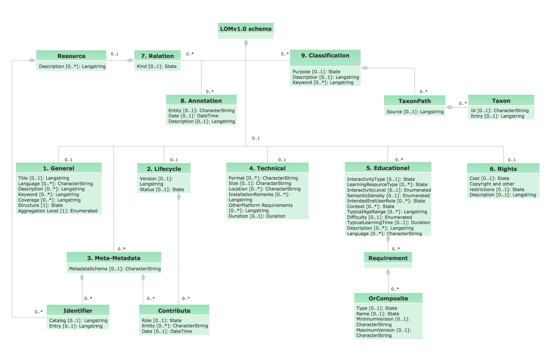
This sample describes the use of the classes, the generalization associations between them, the multiplicity of associations and constraints. Provided UML diagram is one of the examples set that are part of Rapid UML solution.
UML Class Diagram Constructor

The Rapid UML Solution for ConceptDraw DIAGRAM includes the UML Class Diagram library that helps you to design the UML Class Diagram quick and easy. You can simply and quickly drop the ready-to-use objects from the library into your document to create the UML Class Diagram.
UML Class Diagram Notation

UML Notation

Two types of diagrams are used in UML: Structure Diagrams and Behavior Diagrams. Behavior Diagrams represent the processes proceeding in a modeled environment. Structure Diagrams represent the elements that compose the system.
UML Use Case Diagram. Design Elements


UML Class Diagram. Design Elements

OMT Method

All diagrams produced with ConceptDraw DIAGRAM are vector graphic documents and are available for reviewing, modifying, and converting to a variety of formats (image, HTML, PDF file, MS PowerPoint Presentation, Adobe Flash or MS Visio XML).
UML Diagram for System

UML Class Diagram Example - Apartment Plan

This sample show the detailed plan of the apartment and is used by building companies, design apartments, real estate agencies, at the buying / selling of the realty.
UML Diagram Editor
- UML Class Diagram Generalization Example UML Diagrams | UML ...
- Entity Relationship Diagram Symbols | UML Class Diagram ...
- UML Class Diagram Generalization Example UML Diagrams ...
- UML Diagram | UML Class Diagram Generalization Example UML ...
- UML Class Diagrams . Diagramming Software for Design UML ...
- Introductory Guide to Rapid UML Solution | Rapid UML | UML Class ...
- Diagramming Software for Design UML Object Diagrams | Example ...
- How To Create Class Diagram In Visio
- Crow's Foot Notation | Uml Cardinality Notation
- Class UML Diagram for Bank Account System | Bank UML Diagram ...
- ERD | Entity Relationship Diagrams, ERD Software for Mac and Win
- Flowchart | Basic Flowchart Symbols and Meaning
- Flowchart | Flowchart Design - Symbols, Shapes, Stencils and Icons
- Flowchart | Flow Chart Symbols
- Electrical | Electrical Drawing - Wiring and Circuits Schematics
- Flowchart | Common Flowchart Symbols
- Flowchart | Common Flowchart Symbols