UML Class Diagram Notation

Class Diagram Tool

UML Flowchart Symbols

The Rapid UML solution for ConceptDraw DIAGRAM software offers diversity of UML flowchart symbols for drawing all types of UML diagrams.
UML Class Diagram Example - Apartment Plan

This sample show the detailed plan of the apartment and is used by building companies, design apartments, real estate agencies, at the buying / selling of the realty.
What Is a Circle Spoke Diagram

UML Class Diagram Constructor

The Rapid UML Solution for ConceptDraw DIAGRAM includes the UML Class Diagram library that helps you to design the UML Class Diagram quick and easy. You can simply and quickly drop the ready-to-use objects from the library into your document to create the UML Class Diagram.
Software Diagram Examples and Templates

Software Development area of ConceptDraw Solution Park provides 5 solutions:
Data Flow Diagrams, Entity-Relationship Diagram (ERD), Graphic User Interface, IDEFO Diagrams, Rapid UML.
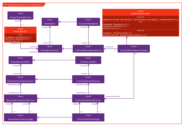
This example was drawn on the base of figure 1 on the webpage "Template: OASIS:FunctionalBreakdownStructure" from the OASIS website.
"The FunctionalBreakdownStructure template describes how to represent a relationship between a FunctionalElementDefinition and another FunctionalElementDefinition that is a constituent.
The SysML Block Definition diagram in Figure 1 shows how a functional breakdown is represented in the PLCS PSM."
[docs.oasis-open.org/ plcs/ plcslib/ v1.0/ csprd01/ data/ contexts/ OASIS/ templates/ FunctionalBreakdownStructure/ template.html]
"A block definition diagram is based on the UML class diagram, with restrictions and extensions as defined by SysML." [omg.org/ spec/ SysML/ 1.3/ PDF]
The example "SysML block definition diagram - Function Breakdown model" was drawn using the ConceptDraw PRO diagramming and vector drawing software extended with the SysML solution from the Software Development area of ConceptDraw Solution Park.
Example of SysML BDD
Bank UML Diagram

UML Tool & UML Diagram Examples

Solution RapidUML from Software Development area of ConceptDraw Solution Park provides templates, examples and 13 vector stencils libraries for drawing all types of UML 1.x and 2.x diagrams using ConceptDraw DIAGRAM diagramming and vector drawing software.
Use these UML diagram templates and examples to quickly start drawing your own UML diagrams.
UML Class Diagram Tutorial

How To Create a Workflow Diagram

The fastest way to create a workflow diagram is using pre-designed workflow template. ConceptDraw DIAGRAM with the Workflow Diagrams solution delivers rich set of workflow diagram templates you may start from.
Bank Sequence Diagram

Transportation Infographics

Components of ER Diagram

UML Diagram for System

User Interface Design Examples

How to draw Metro Map style infographics? (Los Angeles)

This is a one-click tool to add stations to the map. It lets you control the direction in which you create new stations, change lengths, and add text labels and icons. It contains Lines, Stations, and Landmarks objects.
Banking System

Entity Relationship Diagram Symbols

ERD symbols used for professional ERD drawing are collected in libraries from the Entity-Relationship Diagram (ERD) solution for ConceptDraw DIAGRAM.
- Class UML Diagram for Bank Account System | ATM UML Diagrams ...
- UML for Bank | UML Use Case Diagram Example . Services UML ...
- UML Class Diagram Example for GoodsTransportation System ...
- UML Class Diagram Example - Apartment Plan | UML Class ...
- UML Class Diagram Notation | UML Tool & UML Diagram Examples ...
- ATM UML Diagrams | Class Diagram For Atm System Pdf
- Class Diagram For Hospital Management System Pdf
- Use Case Diagram For Pharmacy Management System Pdf
- UML Use Case Diagram Example . Social Networking Sites Project ...
- UML Class Diagram Notation
- UML Class Diagram Notation
- Use Case Diagram For Pharmacy Management System Pdf
- Class Diagram For Library Management System Pdf
- UML Class Diagram Example for Transport System | UML Use Case ...
- ATM UML Diagrams | Uml Diagrams For Banking System Pdf
- UML Class Diagram Notation | UML Use Case Diagram Example ...
- Bank Sequence Diagram | Bank UML Diagram | Banking System ...
- Free Download Use Case Diagram On Medical Store Management
- UML Use Case Diagram Example Social Networking Sites Project ...
- Diagramming Software for Design UML Activity Diagrams | UML ...
- ERD | Entity Relationship Diagrams, ERD Software for Mac and Win
- Flowchart | Basic Flowchart Symbols and Meaning
- Flowchart | Flowchart Design - Symbols, Shapes, Stencils and Icons
- Flowchart | Flow Chart Symbols
- Electrical | Electrical Drawing - Wiring and Circuits Schematics
- Flowchart | Common Flowchart Symbols
- Flowchart | Common Flowchart Symbols