HelpDesk
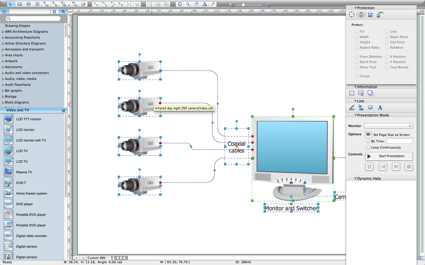
How to Create a CCTV Diagram

CCTV diagram should include the scheme of strategic placement of video cameras, which capture and transmit videos to either a private network of monitors for real-time viewing or to a video recorder for later reference. CCTV is commonly used for surveillance and security purposes. Using ConceptDraw DIAGRAM with the Security and Access Plans Solution lets you create professional looking video surveillance CCTV system plans, security plans, and access schemes.
How To Create CCTV Network Diagram

Developing and installing CCTV system is a time-consuming process. It also requires certain knowledge and skills. ConceptDraw is a solution of setting video cameras rationally. You can achieve two aims at once: CCTV Design Tool saves your time and your money and helps you make professional video surveillance system.
CCTV Network Diagram Software
CCTV Network Example
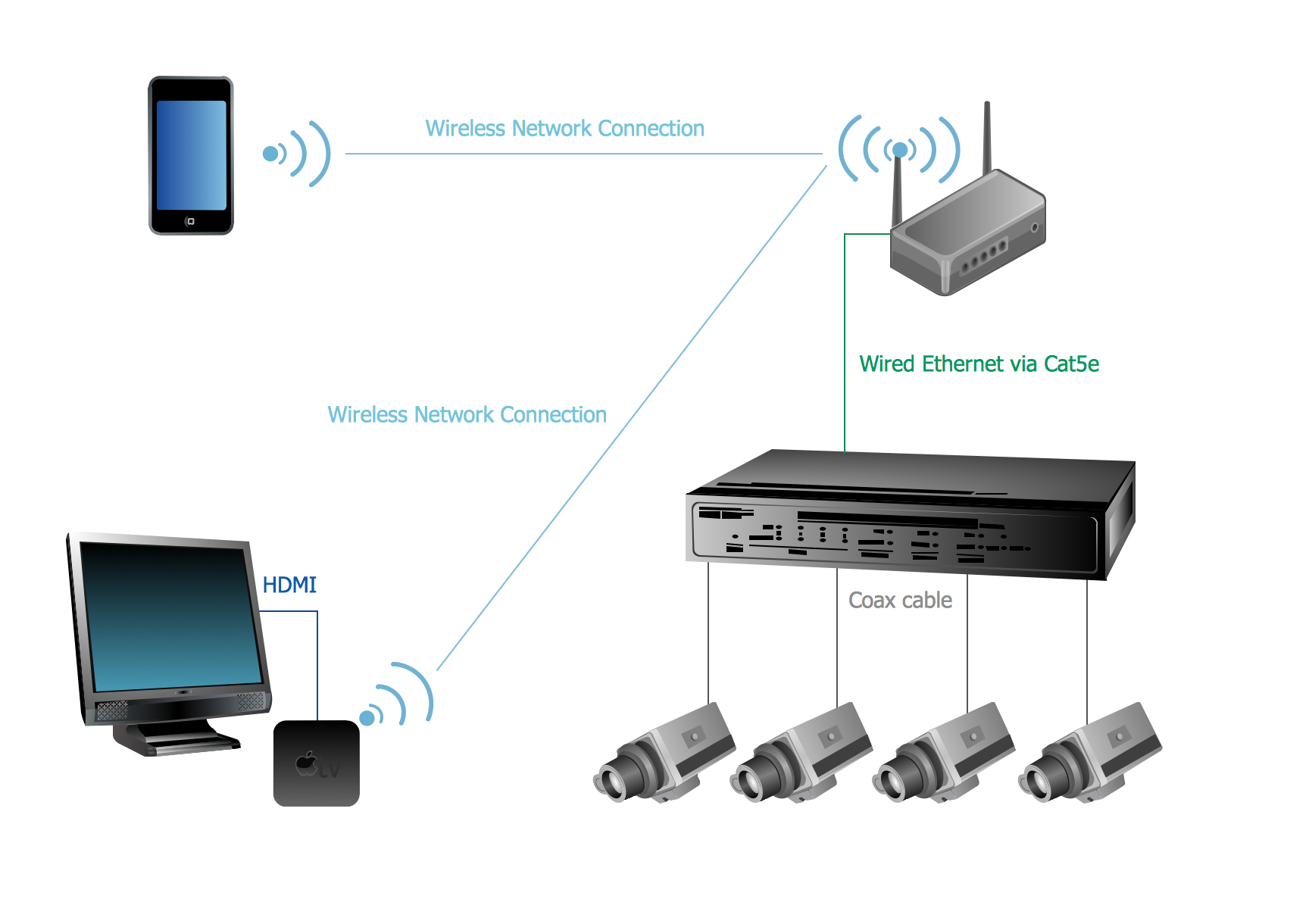
CCTV Surveillance System Diagram. CCTV Network Diagram Example
ConceptDraw DIAGRAM Network Diagram Tool


Cisco LAN. Cisco icons, shapes, stencils and symbols

Network Diagram Software Backbone Network


 Security and Access Plans
The Security and Access Plans solution may be utilized in order to develop detailed equipment and cabling layout plans, blueprints, and wiring diagrams on internal and external security and access control systems, video surveillance and closed-circuit television (CCTV) systems. IT specialists, security managers, and other guards may use it to quickly design security plans and access plans, security chart, physical security plan, access chart, or access scheme on desire.
Export from ConceptDraw DIAGRAM Document to MS Visio® XML

Now you can share your ConceptDraw documents with MS Visio users.

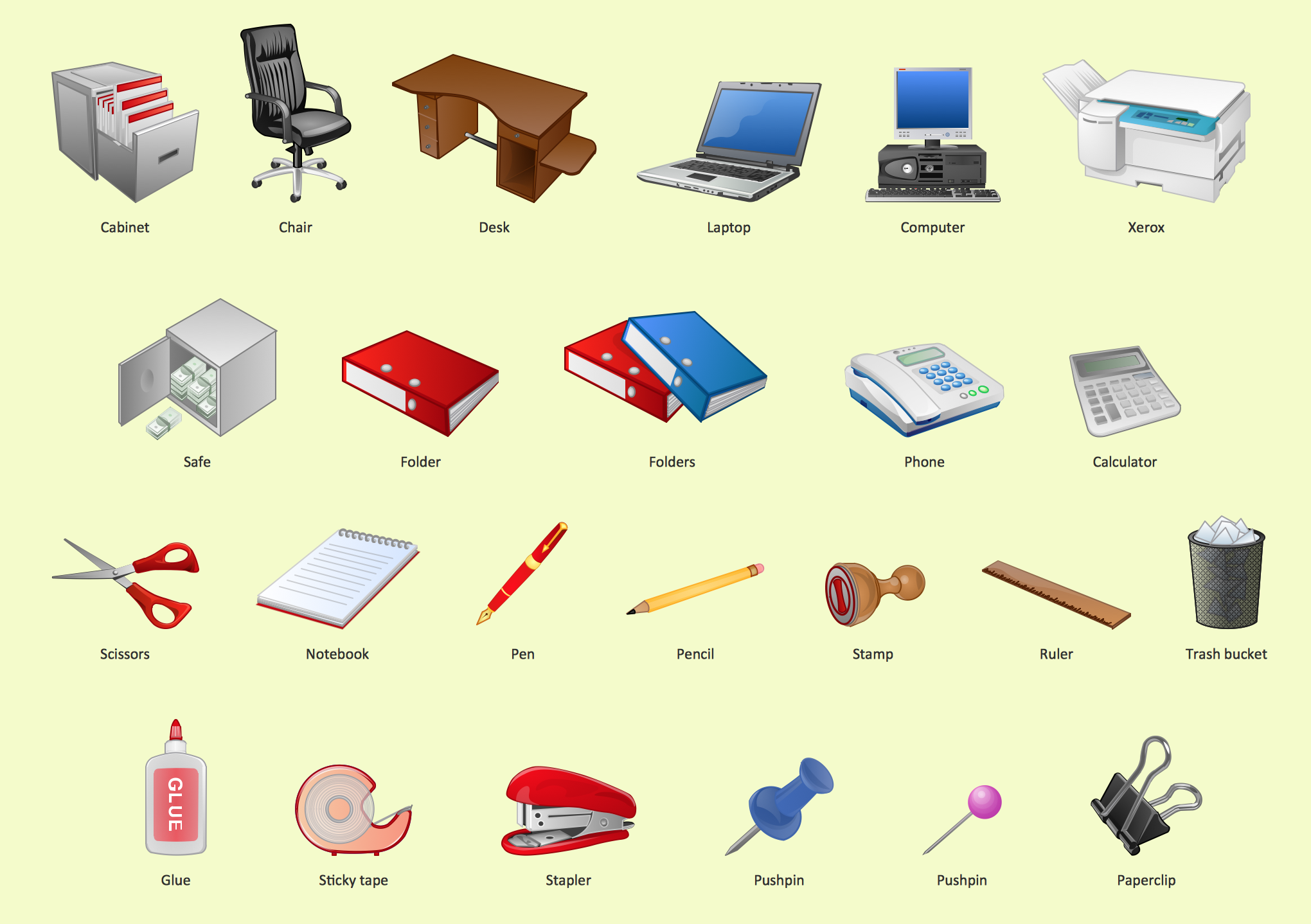
Office - Design Elements
Daisy Chain Network Topology

A Daisy Chain is the simple computer network. It is the easiest way to add more Ethernet devices into the network. In the Daisy Chain network one computer is connected to the next without any intervening devices, thus the message is sent from one computer to the next and then to the next and so on. A Daisy Chain can be linear or ring
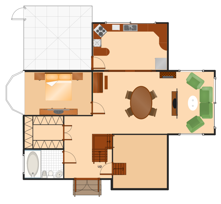
How To Make a Floor Plan
IDEF1X Standard

UML Class Diagram Example for Transport System
This sample shows the transport protocol mappings for SNMP (Simple Network Management Protocol), the classes of the transport system and relationships between them and is used in IP network.
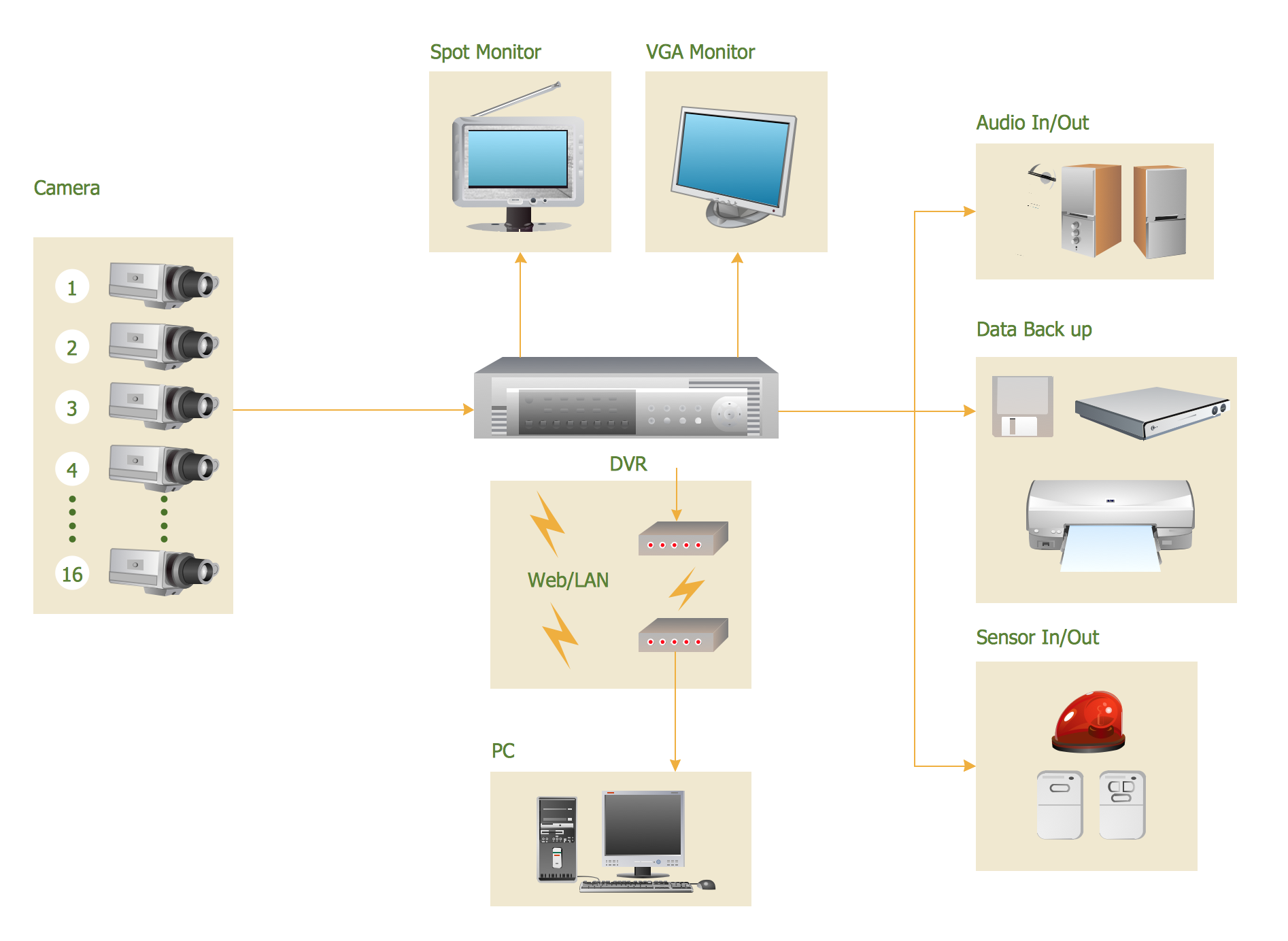
- Basic CCTV System Diagram . CCTV Network Diagram Example ...
- How To Create CCTV Network Diagram
- CCTV Network Example | Camera layout schematic | How to Create ...
- Cctv Camera Installation Sample Circuit Pdf
- How to Create a CCTV Diagram in ConceptDraw PRO | CCTV ...
- Cctv Cameras Circuit Diagram
- Simple Circuit Diagram On Cctv Installation
- Installation Schematics Of Cctv Camera
- Cctv Circuit Diagram Symbols
- Cctv Camera Installation Wiring Diagram
- Diagram Cctv Cameras Installation
- Download Circuit Diagram Of A Cctv Camera
- Cctv Camera Installation Diagram
- Cctv Camera Installation Process
- Circuit Daigram Cctv Camra Installation
- Cctv Camera Circuit Diagram Pdf
- Cctv Installation Process Circuit Diagram
- Cc Camera Install Diagram
- Security and Access Plans | How To Install Cctv Camera Diagram
- Cctv Circuit Diagram Pdf
- ERD | Entity Relationship Diagrams, ERD Software for Mac and Win
- Flowchart | Basic Flowchart Symbols and Meaning
- Flowchart | Flowchart Design - Symbols, Shapes, Stencils and Icons
- Flowchart | Flow Chart Symbols
- Electrical | Electrical Drawing - Wiring and Circuits Schematics
- Flowchart | Common Flowchart Symbols
- Flowchart | Common Flowchart Symbols