Seating Chart Templates
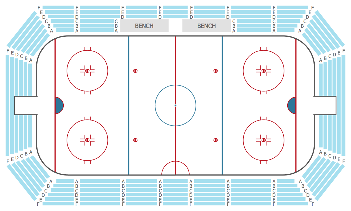
ConceptDraw DIAGRAM diagramming and vector drawing software offers the Seating Plans Solution from the Building Plans Area with extensive drawing tools, predesigned vector shapes and samples which are convenient for using as is or as seating chart templates.Restaurant Floor Plans
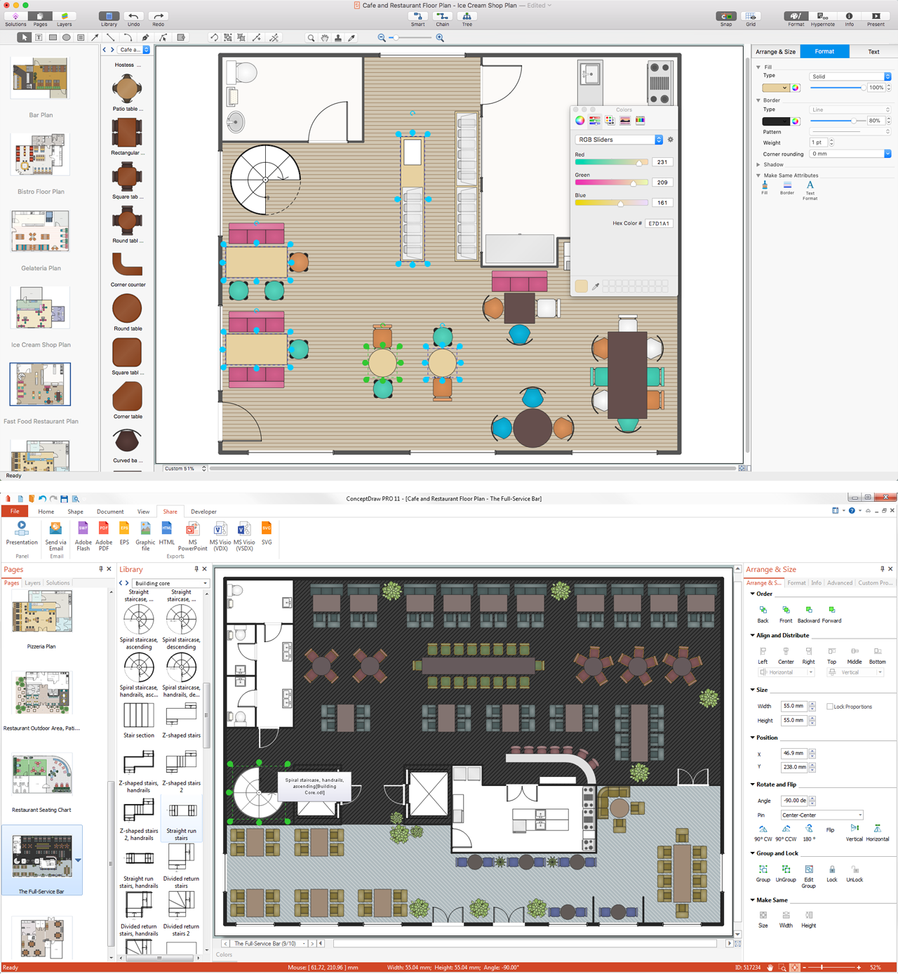
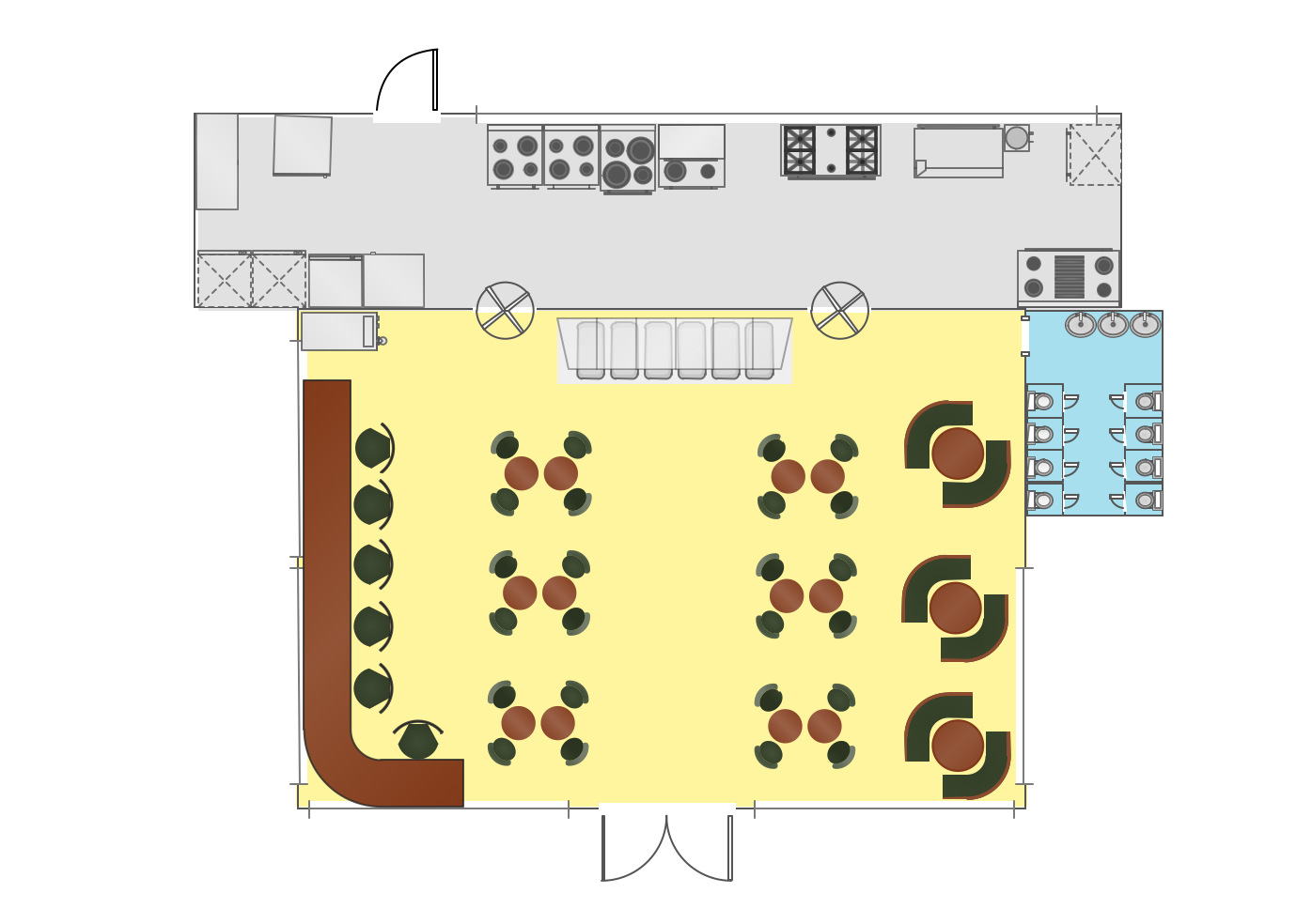
Making design interior restaurant or café floor plan can be hard and very complicated unless you have ConceptDraw DIAGRAM software which can do all drawing for you offering lots of templates, samples of floor plans and many other plans and schemes, including even examples of numerous charts, flowcharts and diagrams.Selecting & Creating Flowcharts
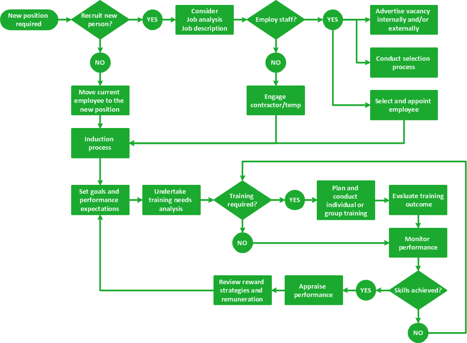
ConceptDraw Flowcharts visualize a process or algorithm of program as step/operation blocks of various shapes connected with arrowed lines showed the process flow direction. They are used to visualize business or technical processes and software algorithms.Café Floor Plan Example
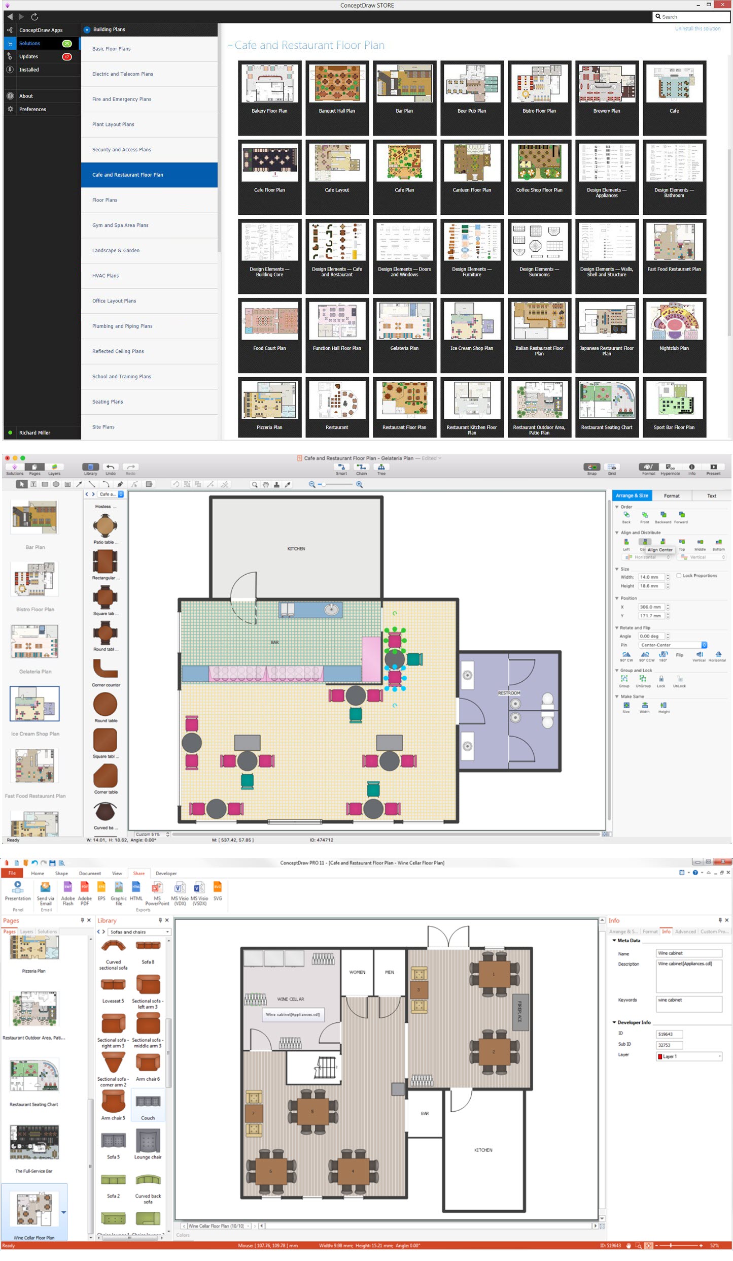
Once you download ConceptDraw DIAGRAM , which is a professional software for designers, you will find so many tools for making your plans, including lots of design stencils, examples and templates that can be helpful in terms of using them as drafts to edit all of them the way you want to end up having great looking professional floor plans.Competitor Analysis
Competitor analysis is a first and obligatory step in elaboration the proper corporate marketing strategy and creating sustainable competitive advantage. Use powerful opportunities of numerous solutions from ConceptDraw Solution Park for designing illustrative diagrams, charts, matrices which are necessary for effective competitor analysis.Affinity Diagram
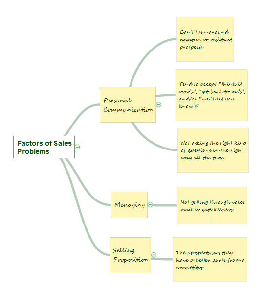
The Affinity Diagram shows the structure of large, complex factors that have an influence on a problem, and then divides them up into a smaller and simpler structure. The Affinity Diagram does not show a causal relationship between the factors. This diagram is designed to prepare the data for further analysis of the cause-effect relationships.Interior Design
Interior design describes a group of various yet related projects that involve turning an interior space into an "effective setting for the range of human activities" that are to take place there. Floor plan shows a view from above, of the relationships between rooms, spaces and other physical features at one level of a structure. It is comfortable for demonstrating interior design ideas.Working as an interior designer who implies that there is more of an emphasis on functional design, the effective use of space and planning, undertaking the projects that include such processes as arranging the basic layout of the spaces within some building, you might find the ConceptDraw DIAGRAM interior design drawing software.
Bubble Chart
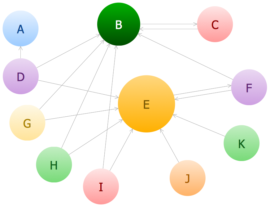
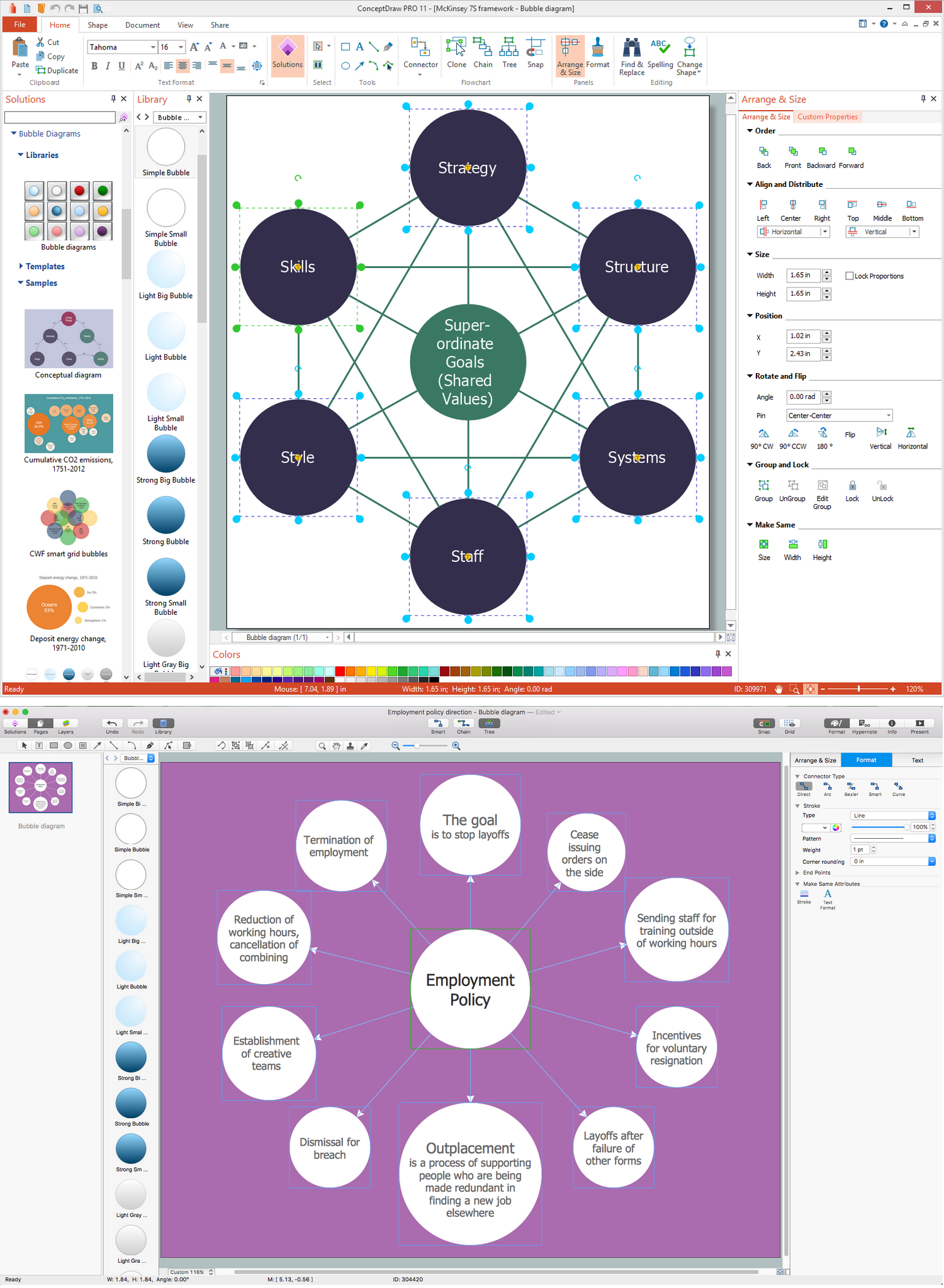
How to design a Bubble Chart? It’s very easy! All that you need is a powerful software. Never before creation of a Bubble Chart wasn’t so easy as now with tools of Bubble Diagrams Solution from the "Diagrams" Area for ConceptDraw Solution Park.Food Court
Food courts are one of the most rapidly developing areas of the restaurant business. ConceptDraw DIAGRAM diagramming and vector drawing software offers a Food Court solution from the Food and Beverage area with wide capabilities for planning, design, developing and advertising of a Food Court.Bubble Chart Maker
ConceptDraw DIAGRAM diagramming and vector drawing software extended with Bubble Diagrams Solution from the "Diagrams" Area is a powerful Bubble Chart Maker.UML Class Diagram Generalization Example UML Diagrams
This sample was created in ConceptDraw DIAGRAM diagramming and vector drawing software using the UML Class Diagram library of the Rapid UML Solution from the Software Development area of ConceptDraw Solution Park.This sample describes the use of the classes, the generalization associations between them, the multiplicity of associations and constraints. Provided UML diagram is one of the examples set that are part of Rapid UML solution.
UML Use Case Diagram Example. Registration System
The use case diagram (behavior scenarios, precedents) is the initial conceptual representation of the system during its design and development. This diagram consists of actors, use cases and relationships between them. When constructing a diagram, common notation elements can also be used: notes and extension mechanisms.This sample was created in ConceptDraw DIAGRAM diagramming and vector drawing software using the UML Use Case Diagram library of the Rapid UML Solution from the Software Development area of ConceptDraw Solution Park.
This sample shows the types of user’s interactions with the system and is used at the registration and working with the database system.
Interaction Overview Diagram
UML Interaction Overview Diagram schematically shows a control flow with nodes and a sequence of activities that can contain interaction or sequence diagrams.
UML Diagram Visio
This sample shows the UML Class Diagram that was created in ConceptDraw DIAGRAM on the Mac and then was opened for editing in MS Visio.Using the 13 libraries of the Rapid UML Solution for ConceptDraw DIAGRAM you can create your own visual vector UML diagrams quick and easy.
Cisco Network Topology. Cisco icons, shapes, stencils and symbols
The Cisco Network Diagrams solution uses Cisco network symbols and Cisco icons to visualize computer networks. Cisco Network Topology is the arrangement of the Cisco symbols that display scheme of computer network.Any Cisco equipment on the network are named like node. Network diagram topology commonly designed within connected nodes. Cisco icons are worldwide acknowledged and mainly established as standard icons for network diagrams. You may use them loosely, but you may not rework them.
The Cisco Network Diagram shows how signals act on the networked devices, or how data routes on the network from one device to the other. There are number of physical network typologies that engineers use while constructing computer networks.
UML Sample Project
Unified Modeling Language (UML) is a graphical modeling language for describing, visualizing, projecting and documenting of object oriented systems. UML digram is used for modeling of organizations and their business processes, for development the big projects, the complex software applications. Comprehensive UML diagram allows to create the set of interrelated documents that gives the complete visual representation of the modeling system.- Banquet Hall Plan Software
- Cooking Recipes | Dinner Recipes | | Kitchen Work Flow Chart
- Examples of Flowcharts, Org Charts and More | Draw Company ...
- Book Keeping Chart Diagram
- Hotel Plan. Hotel Plan Examples | How to Draw an Organization ...
- How to Add a Bubble Diagram to MS Word | Bubble Chart | How To ...
- Organizational Chart Template | Matrix Organization Structure ...
- Schedule pie chart - Daily action plan | Chart Maker for ...
- Competitive feature comparison matrix chart - Digital scouting cameras
- Organizational Structure | Create Organizational Chart ...
- Organizational Structure | Create Organizational Chart ...
- What is Gantt Chart (historical reference) | PERT Chart Software ...
- Bubble Charts | How To Create a Bubble Chart | Bubble Map Maker ...
- How to Create a Floor Plan for the Classroom | Interior Design ...
- How to Draw a Gantt Chart | PM Planning | Software development ...
- Bubble diagrams with ConceptDraw DIAGRAM | Bubble Chart | How ...
- How to Create Organizational Chart Quickly | Organizational Charts ...
- Basketball | How to Create Organizational Chart Using Management ...
- How to Add a Cross-Functional Flowchart to a PowerPoint ...
- How to Draw a Bubble Chart | How To Create a Bubble Chart ...
- ERD | Entity Relationship Diagrams, ERD Software for Mac and Win
- Flowchart | Basic Flowchart Symbols and Meaning
- Flowchart | Flowchart Design - Symbols, Shapes, Stencils and Icons
- Flowchart | Flow Chart Symbols
- Electrical | Electrical Drawing - Wiring and Circuits Schematics
- Flowchart | Common Flowchart Symbols
- Flowchart | Common Flowchart Symbols
