Entity Relationship Diagram Examples

ConceptDraw DIAGRAM diagramming and vector drawing software gives the ability to describe a database using the Entity-Relationship model. Entity-Relationship Diagram(ERD) solution from the Software Development area supplies the ConceptDraw DIAGRAM with icons advocated by Chen's and Crow’s Foot notation that can be used when describing a database.

The vector stencils library "Active Directory" contains 20 symbols of Active Directory elements for drawing AD network diagrams. It helps network and system administrators to visualize Microsoft Windows Active Directory structures for network design, installation and maintainance.
"An Active Directory structure is an arrangement of information about objects. The objects fall into two broad categories: resources (e.g., printers) and security principals (user or computer accounts and groups). Security principals are assigned unique security identifiers (SIDs).
Each object represents a single entity - whether a user, a computer, a printer, or a group - and its attributes. Certain objects can contain other objects. An object is uniquely identified by its name and has a set of attributes - the characteristics and information that the object represents - defined by a schema, which also determines the kinds of objects that can be stored in Active Directory.
The schema object lets administrators extend or modify the schema when necessary. However, because each schema object is integral to the definition of Active Directory objects, deactivating or changing these objects can fundamentally change or disrupt a deployment. Schema changes automatically propagate throughout the system. Once created, an object can only be deactivated - not deleted. Changing the schema usually requires planning. Sites are implemented as a set of well-connected subnets." [Active Directory. Wikipedia]
The AD symbols example "Active Directory - Vector stencils library" was created using the ConceptDraw PRO diagramming and vector drawing software extended with the Active Directory Diagrams solution from the Computer and Networks area of ConceptDraw Solution Park.
www.conceptdraw.com/ solution-park/ active-directory-diagrams
Domain
Computer

User

Group

Container

Print queue
Contact

Organizational unit

Policy

Volume
Generic object

Site

Site link

Site link bridge

Server

NTDS site settings
IP subnet

Certificate template

Licensing site

Connection

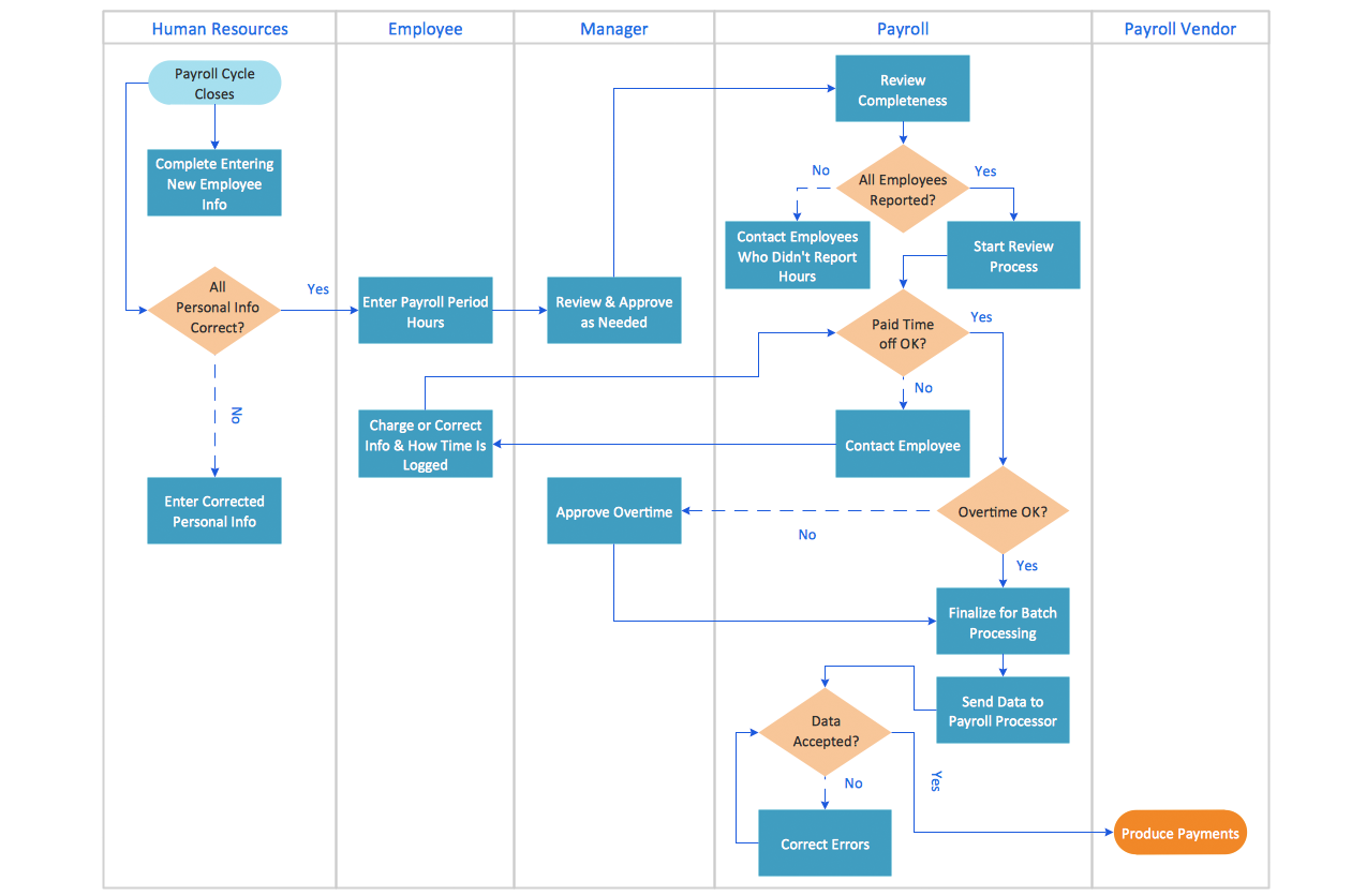
How to Draw an Effective Flowchart
Entity-Relationship Diagram

UML Use Case Diagram Example. Registration System

This sample was created in ConceptDraw DIAGRAM diagramming and vector drawing software using the UML Use Case Diagram library of the Rapid UML Solution from the Software Development area of ConceptDraw Solution Park.
This sample shows the types of user’s interactions with the system and is used at the registration and working with the database system.
Telecommunication networks. Computer and Network Examples

This example was created in ConceptDraw DIAGRAM using the Computer and Networks Area of ConceptDraw Solution Park and shows the Telecommunications network.

 Active Directory Diagrams
Active Directory Diagrams solution significantly extends the capabilities of ConceptDraw DIAGRAM software with special Active Directory samples, convenient template and libraries of Active Directory vector stencils, common icons of sites and services, icons of LDPA elements, which were developed to help you in planning and modelling network structures and network topologies, in designing excellently looking Active Directory diagrams, Active Directory Structure diagrams, and Active Directory Services diagram, which are perfect way to visualize detailed structures of Microsoft Windows networks, Active Directory Domain topology, Active Directory Site topology, Organizational Units (OU), and Exchange Server organization.
Software Diagram Examples and Templates

Software Development area of ConceptDraw Solution Park provides 5 solutions:
Data Flow Diagrams, Entity-Relationship Diagram (ERD), Graphic User Interface, IDEFO Diagrams, Rapid UML.
Sign Making Software
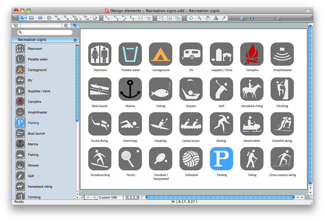
Sign making software is very useful tool for professional sign-making business. Use ConceptDraw DIAGRAM and make sure that now sign making is easier and timesaving than ever!
Entity Relationship Software

The vector graphic diagrams produced when using the ConceptDraw ERD solution can be used in whitepapers, presentations, datasheets, posters, or any technical materials.
It is convenient to design ER Diagrams using ConceptDraw DIAGRAM software. ConceptDraw DIAGRAM extended with the Entity-Relationship Diagram (ERD) solution supports Chen's and Crow’s Foot notations that are often used to describe database structure.
- Certificate Courses Templates For Students
- Professional Certificate Maker
- Windows Azure | Active Directory Diagram | AWS Architecture ...
- Printing Certificates Software
- Skating Certificate Templates
- Certificate template
- Workflow diagram - Template | Stages of personnel certification ...
- Sign Making Software | Free Award Certificates Templates To ...
- Wide area network (WAN) topology. Computer and Network ...
- Marketing Diagrams | In Honor Of Certificate Template
- ERD | Entity Relationship Diagrams, ERD Software for Mac and Win
- Flowchart | Basic Flowchart Symbols and Meaning
- Flowchart | Flowchart Design - Symbols, Shapes, Stencils and Icons
- Flowchart | Flow Chart Symbols
- Electrical | Electrical Drawing - Wiring and Circuits Schematics
- Flowchart | Common Flowchart Symbols
- Flowchart | Common Flowchart Symbols