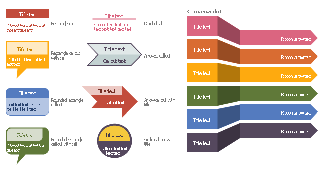
The vector stencils library "Education titled callouts" contains 14 titled callout blocks.
Use it to design your educational infograms.
"In publishing, a call-out or callout is a short string of text connected by a line, arrow, or similar graphic to a feature of an illustration or technical drawing, and giving information about that feature. The term is also used to describe a short piece of text set in larger type than the rest of the page and intended to attract attention.
A similar device in word processing is a special text box with or without a small "tail" that can be pointed to different locations on a document." [Callout. Wikipedia]
The shapes example "Design elements - Education titled callouts" was created using the ConceptDraw PRO diagramming and vector drawing software extended with the Education Infographics solition from the area "Business Infographics" in ConceptDraw Solution Park.
Titled callout blocks
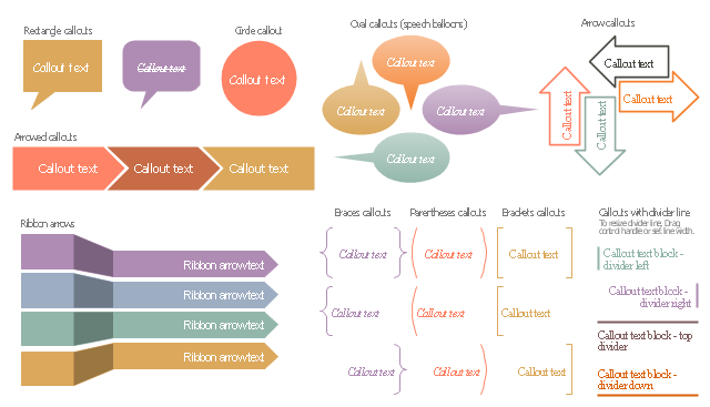
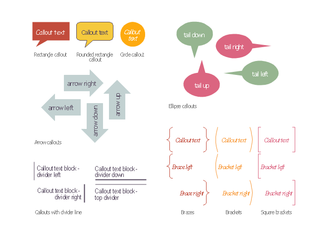
The vector stencils library "Callout blocks" contains 31 callouts, speech balloons and brackets for creating marketing infograms.
"In publishing, a call-out or callout is a short string of text connected by a line, arrow, or similar graphic to a feature of an illustration or technical drawing, and giving information about that feature. The term is also used to describe a short piece of text set in larger type than the rest of the page and intended to attract attention.
A similar device in word processing is a special text box with or without a small "tail" that can be pointed to different locations on a document." [Callout. Wikipedia]
The shapes example "Design elements - Callout blocks" was created using the ConceptDraw PRO diagramming and vector drawing software extended with the Marketing Infographics solition from the area "Business Infographics" in ConceptDraw Solution Park.
Callouts, speech balloons and brackets
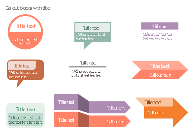
The vector stencils library "Titled callouts" contains 10 callout blocks with title and text.
Use it to design your marketing infograms.
The shapes example "Design elements - Titled callouts" was created using the ConceptDraw PRO diagramming and vector drawing software extended with the Marketing Infographics solition from the area "Business Infographics" in ConceptDraw Solution Park.
Use it to design your marketing infograms.
The shapes example "Design elements - Titled callouts" was created using the ConceptDraw PRO diagramming and vector drawing software extended with the Marketing Infographics solition from the area "Business Infographics" in ConceptDraw Solution Park.
Callout blocks with title and text
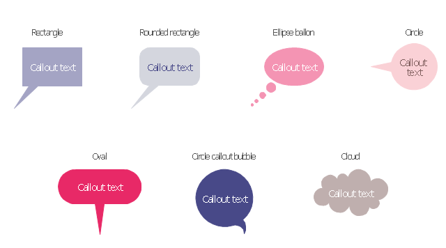
The vector stencils library "Callout" contains 7 callout shapes for drawing typography infographics.
"In publishing, a call-out or callout is a short string of text connected by a line, arrow, or similar graphic to a feature of an illustration or technical drawing, and giving information about that feature. The term is also used to describe a short piece of text set in larger type than the rest of the page and intended to attract attention.
A similar device in word processing is a special text box with or without a small "tail" that can be pointed to different locations on a document." [Callout. Wikipedia]
The example "Design elements - Callouts" was created using the ConceptDraw PRO diagramming and vector drawing software extended with the Typography Infographics solition from the area "What is infographics" in ConceptDraw Solution Park.
Typography infographics elements - Callouts
The vector stencils library "Dimensioning and tolerancing" contains 45 symbols of geometric dimensions and mechanical tolerances, geometric symbols, callouts, and text boxes and inserts.
Use these geometric dimensioning and tolerancing (GD&T) shapes to create annotated mechanical drawings in the ConceptDraw PRO diagramming and vector drawing software extended with the Mechanical Engineering solution from the Engineering area of ConceptDraw Solution Park.
www.conceptdraw.com/ solution-park/ engineering-mechanical
Datum (old)
-dimensioning-and-tolerancing---vector-stencils-library.png--diagram-flowchart-example.png)
Box callout

Datum symbol

Callout

All around callout

Text block

2 datum frame

Simple frame

Basic frame

1 datum frame

3 datum frame

Straightness

Flatness

Line profile

Circularity

Cylindricity

Surface profile

Position

Concentricity

Symmetry

Parallelism

Perpendicularity

Angularity

Material condition

Arc length

Diameter

Counterbore/ spotface

Countersink

Depth

Slope

Conical taper

Statistical tolerance

Datum (new)
-dimensioning-and-tolerancing---vector-stencils-library.png--diagram-flowchart-example.png)
Datum (new) 2
-2-dimensioning-and-tolerancing---vector-stencils-library.png--diagram-flowchart-example.png)
Target point

Target line

Target area (circle)
-dimensioning-and-tolerancing---vector-stencils-library.png--diagram-flowchart-example.png)
Target area (rectangle)
-dimensioning-and-tolerancing---vector-stencils-library.png--diagram-flowchart-example.png)
Total runout

Total runout 2

Circular runout

Circular runout 2

Surface finish

Surface finish, removal process

Surface finish, no process permitted

This vector stencils library contains 22 symbols of process annotations for setting automatic labels to display a datasheet field for a pipeline shape, labels, captions, outlines, off-sheet labels, text balloons, annotations, outlines, tags, and descriptions.
Use these shapes for drawing Process Flow Diagrams (PFD) and Piping and Instrumentation Diagrams (P&ID) in the ConceptDraw PRO software extended with the Chemical and Process Engineering solution from the Chemical and Process Engineering area of ConceptDraw Solution Park.
www.conceptdraw.com/ solution-park/ engineering-chemical-process
Interface point

Interface point 2 (1st half filled)
-process-annotations---vector-stencils-library.png--diagram-flowchart-example.png)
Interface point 3 (2nd half filled)
-process-annotations---vector-stencils-library.png--diagram-flowchart-example.png)
Interface point 4

Interface point 5 (1st half filled)
-process-annotations---vector-stencils-library.png--diagram-flowchart-example.png)
Interface point 6 (2nd half filled)
-process-annotations---vector-stencils-library.png--diagram-flowchart-example.png)
Slope

Off-sheet label 1

Off-sheet label 2

Off-sheet label 3

Callout 1

Callout 2

Callout 3

Callout 4

Callout 5

Callout 6

8 pt text and line

10 pt text and line

12 pt text and line

12 pt Arial text block

10 pt Arial text block

8 pt Arial text block

The vector stencils library "Education callouts" contains 24 shapes of callouts, speech balloons, arrows, braces and brackets.
Use it to design your education infograms.
"Speech balloons (also speech bubbles, dialogue balloons or word balloons) are a graphic convention used most commonly in comic books, comic strips and cartoons to allow words (and much less often, pictures) to be understood as representing the speech or thoughts of a given character in the comic. There is often a formal distinction between the balloon that indicates thoughts and the one that indicates words spoken aloud: the balloon that conveys subjective thoughts is often referred to as a thought bubble." [Speech balloon. Wikipedia]
The shapes example "Design elements - Education callouts" was created using the ConceptDraw PRO diagramming and vector drawing software extended with the Education Infographics solition from the area "Business Infographics" in ConceptDraw Solution Park.
Callouts, speech balloons, arrows, braces, brackets
This vector stencils library contains 22 symbols of process annotations for setting automatic labels to display a datasheet field for a pipeline shape, labels, captions, outlines, off-sheet labels, text balloons, annotations, outlines, tags, and descriptions.
Use these shapes for drawing Process Flow Diagrams (PFD) and Piping and Instrumentation Diagrams (P&ID) in the ConceptDraw PRO software extended with the Chemical and Process Engineering solution from the Chemical and Process Engineering area of ConceptDraw Solution Park.
www.conceptdraw.com/ solution-park/ engineering-chemical-process
Use these shapes for drawing Process Flow Diagrams (PFD) and Piping and Instrumentation Diagrams (P&ID) in the ConceptDraw PRO software extended with the Chemical and Process Engineering solution from the Chemical and Process Engineering area of ConceptDraw Solution Park.
www.conceptdraw.com/ solution-park/ engineering-chemical-process
Interface point
Interface point 2 (1st half filled)
Interface point 3 (2nd half filled)
Interface point 4
Interface point 5 (1st half filled)
Interface point 6 (2nd half filled)
Slope
Off-sheet label 1
Off-sheet label 2
Off-sheet label 3
Callout 1
Callout 2
Callout 3
Callout 4
Callout 5
Callout 6
8 pt text and line
10 pt text and line
12 pt text and line
12 pt Arial text block
10 pt Arial text block
8 pt Arial text block
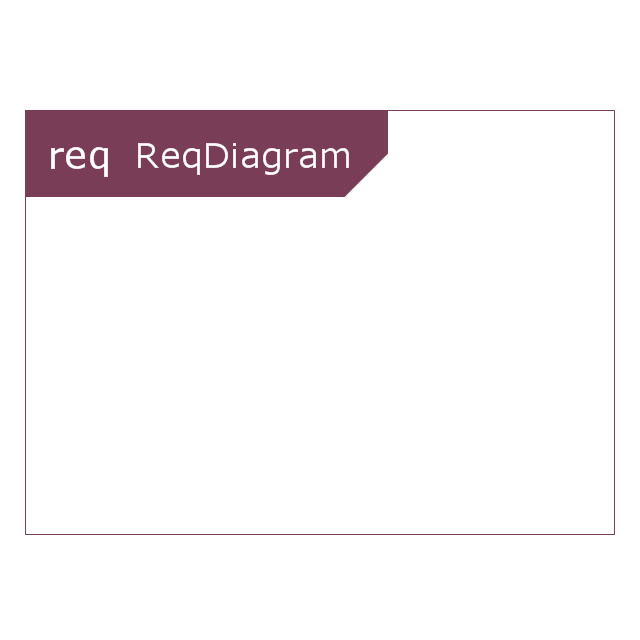
This vector stencils library contains 21 SysML symbols.
Use it to design your requirement diagrams using ConceptDraw PRO diagramming and vector drawing software.
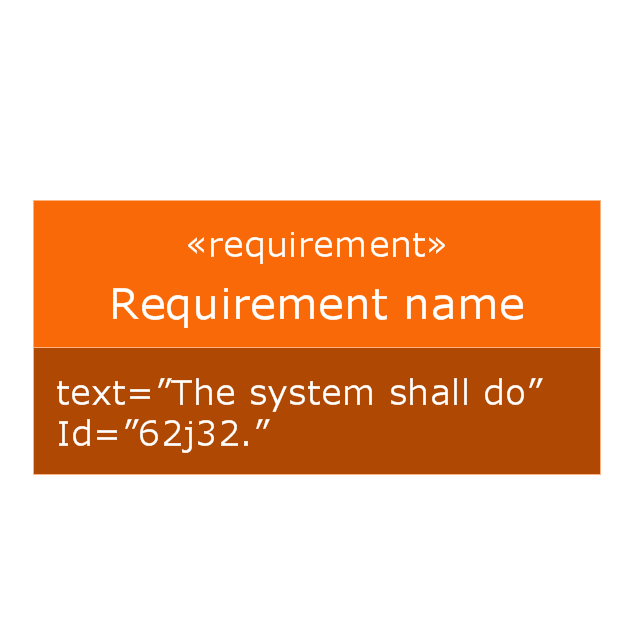
"A requirement specifies a capability or condition that must (or should) be satisfied. A requirement may specify a function that a system must perform or a performance condition a system must achieve. SysML provides modeling constructs to represent text-based requirements and relate them to other modeling elements. The requirements diagram described in this clause can depict the requirements in graphical, tabular, or tree structure format. A requirement can also appear on other diagrams to show its relationship to other modeling elements. The requirements modeling constructs are intended to provide a bridge between traditional requirements management tools and the other SysML models.
A requirement is defined as a stereotype of UML Class subject to a set of constraints. A standard requirement includes properties to specify its unique identifier and text requirement. Additional properties such as verification status, can be specified by the user.
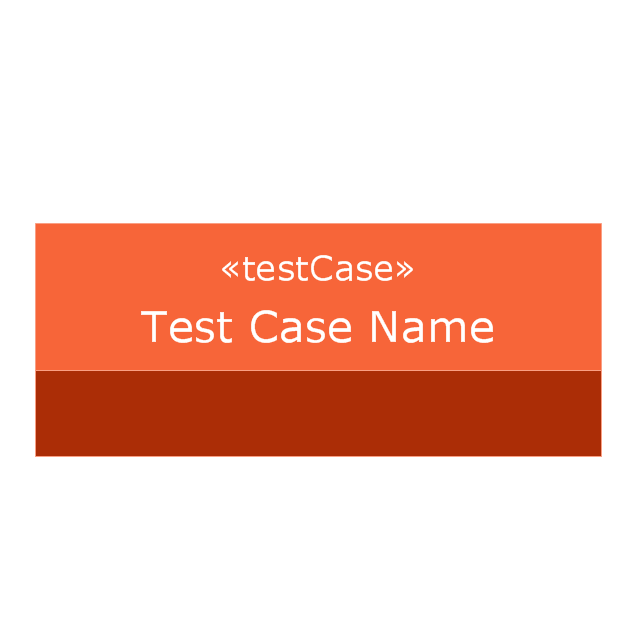
Several requirements relationships are specified that enable the modeler to relate requirements to other requirements as well as to other model elements. These include relationships for defining a requirements hierarchy, deriving requirements, satisfying requirements, verifying requirements, and refining requirements." [www.omg.org/ spec/ SysML/ 1.3/ PDF]
The vector stencils library "Requirement diagram" is included in the SysML solution from the Software Development area of ConceptDraw Solution Park.
Use it to design your requirement diagrams using ConceptDraw PRO diagramming and vector drawing software.
"A requirement specifies a capability or condition that must (or should) be satisfied. A requirement may specify a function that a system must perform or a performance condition a system must achieve. SysML provides modeling constructs to represent text-based requirements and relate them to other modeling elements. The requirements diagram described in this clause can depict the requirements in graphical, tabular, or tree structure format. A requirement can also appear on other diagrams to show its relationship to other modeling elements. The requirements modeling constructs are intended to provide a bridge between traditional requirements management tools and the other SysML models.
A requirement is defined as a stereotype of UML Class subject to a set of constraints. A standard requirement includes properties to specify its unique identifier and text requirement. Additional properties such as verification status, can be specified by the user.
Several requirements relationships are specified that enable the modeler to relate requirements to other requirements as well as to other model elements. These include relationships for defining a requirements hierarchy, deriving requirements, satisfying requirements, verifying requirements, and refining requirements." [www.omg.org/ spec/ SysML/ 1.3/ PDF]
The vector stencils library "Requirement diagram" is included in the SysML solution from the Software Development area of ConceptDraw Solution Park.
Requirement diagram
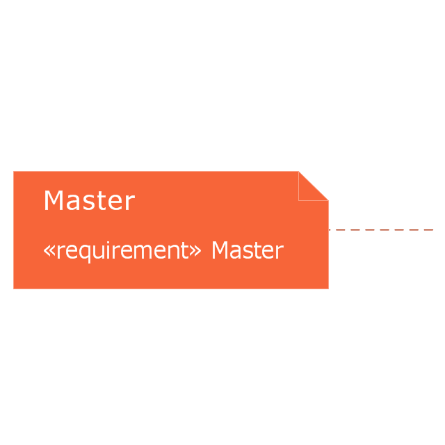
Requirement
Test case
Requirement containment relationship
Copy dependency
Master callout
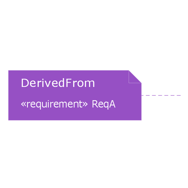
Derive dependency
Derive callout
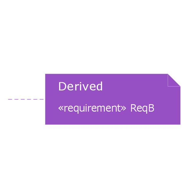
Derive callout 2
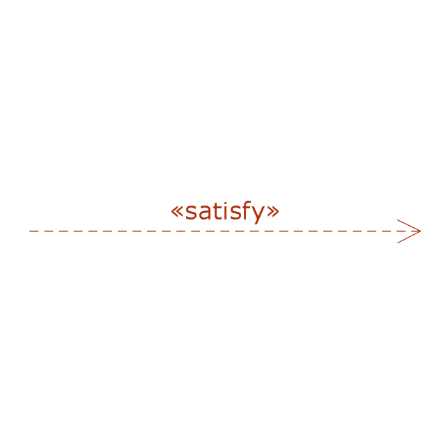
Satisfy dependency
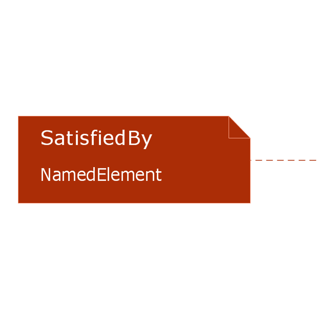
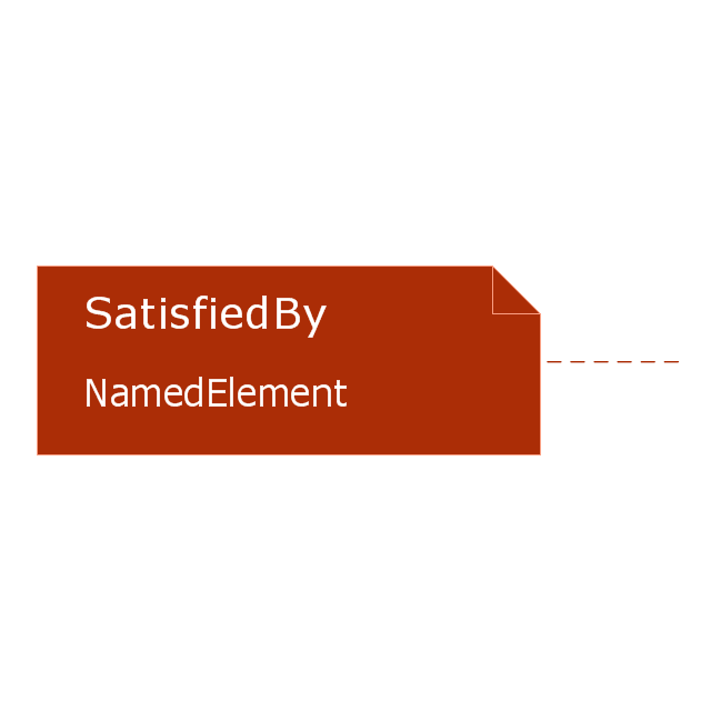
Satisfy callout
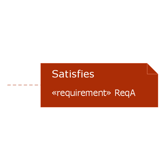
Satisfy callout 2
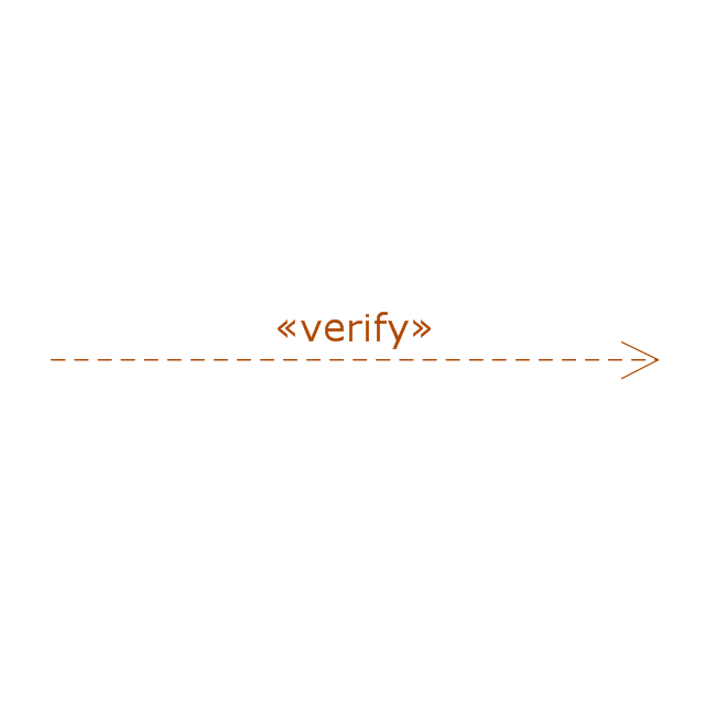
Verify dependency
Verify callout

Verify callout 2
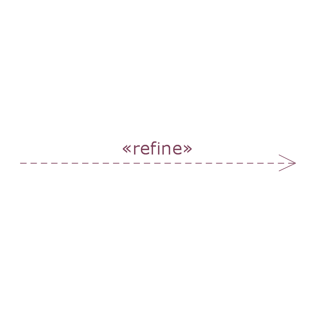
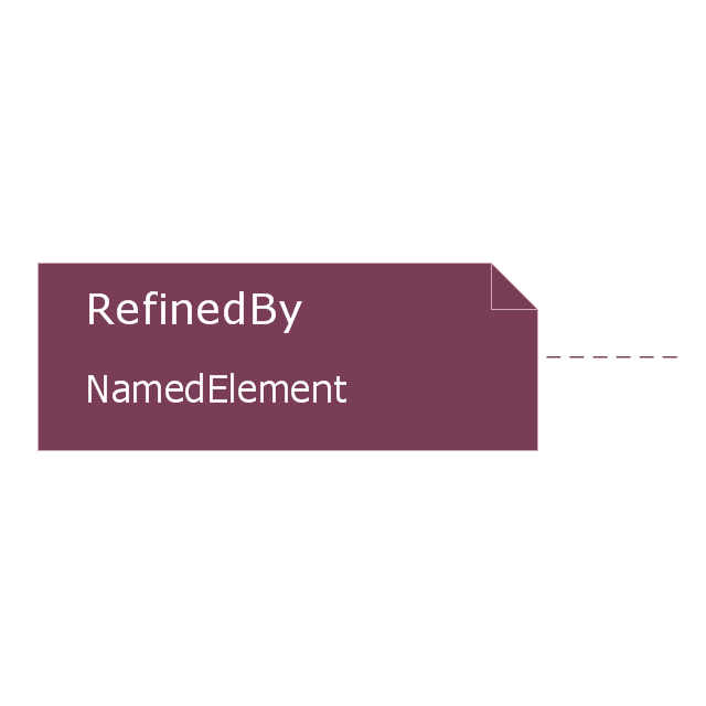
Refine dependency
Refine callout
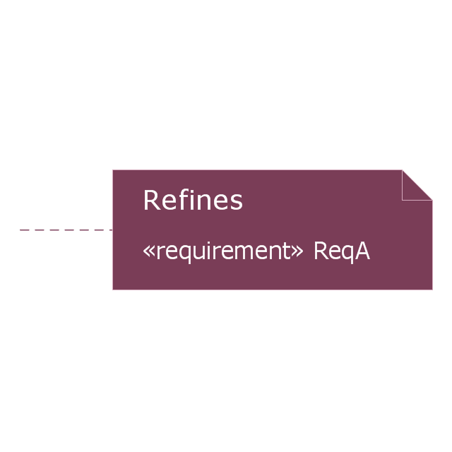
Refine callout 2
Trace dependency
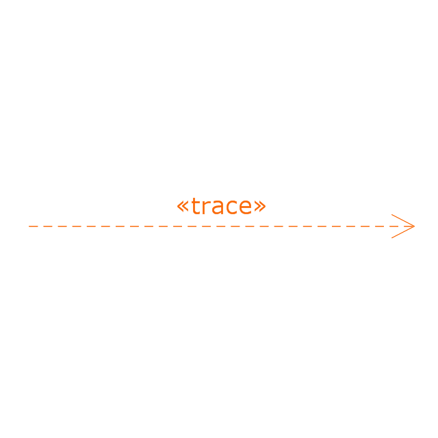
Trace callout
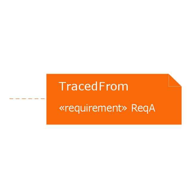
Trace callout 2
This vector stencils library contains 21 SysML symbols.
Use it to design your requirement diagrams using ConceptDraw PRO diagramming and vector drawing software.
"A requirement specifies a capability or condition that must (or should) be satisfied. A requirement may specify a function that a system must perform or a performance condition a system must achieve. SysML provides modeling constructs to represent text-based requirements and relate them to other modeling elements. The requirements diagram described in this clause can depict the requirements in graphical, tabular, or tree structure format. A requirement can also appear on other diagrams to show its relationship to other modeling elements. The requirements modeling constructs are intended to provide a bridge between traditional requirements management tools and the other SysML models.
A requirement is defined as a stereotype of UML Class subject to a set of constraints. A standard requirement includes properties to specify its unique identifier and text requirement. Additional properties such as verification status, can be specified by the user.
Several requirements relationships are specified that enable the modeler to relate requirements to other requirements as well as to other model elements. These include relationships for defining a requirements hierarchy, deriving requirements, satisfying requirements, verifying requirements, and refining requirements." [www.omg.org/ spec/ SysML/ 1.3/ PDF]
The vector stencils library "Requirement diagram" is included in the SysML solution from the Software Development area of ConceptDraw Solution Park.
Requirement diagram
Requirement
Test case
Requirement containment relationship
Copy dependency
Master callout
Derive dependency
Derive callout
Derive callout 2
Satisfy dependency
Satisfy callout
Satisfy callout 2
Verify dependency
Verify callout
Verify callout 2
Refine dependency
Refine callout
Refine callout 2
Trace dependency
Trace callout
Trace callout 2
- Design elements - Education titled callouts | Design elements ...
- Design elements - Callout blocks | Design elements - Education ...
- Design elements - Callouts | Design elements - Education titled ...
- Design elements - Education titled callouts
- Design elements - Management title blocks | Design elements ...
- | | | Callout
- Design elements - Callouts
- Basic Flowchart Symbols and Meaning | ERD Symbols and ...
- Callout Diagram
- Callout 5
- Callout 3
- Callout 6
- Callout 4
- Basic Flowchart Symbols and Meaning | ConceptDraw Arrows10 ...
- Mechanical Drawing Symbols | Weld Symbols Callout Drafting
- How to Show the Relationship Between Topics | Cloud Callout
- Vector stencils library - Requirement diagram
- Derive callout 2
- Vector stencils library - Requirement diagram
- Satisfy callout
- ERD | Entity Relationship Diagrams, ERD Software for Mac and Win
- Flowchart | Basic Flowchart Symbols and Meaning
- Flowchart | Flowchart Design - Symbols, Shapes, Stencils and Icons
- Flowchart | Flow Chart Symbols
- Electrical | Electrical Drawing - Wiring and Circuits Schematics
- Flowchart | Common Flowchart Symbols
- Flowchart | Common Flowchart Symbols