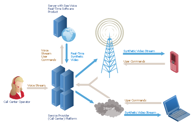
"A call centre or call center is a centralised office used for the purpose of receiving or transmitting a large volume of requests by telephone. An inbound call centre is operated by a company to administer incoming product support or information inquiries from consumers. Outbound call centers are operated for telemarketing, solicitation of charitable or political donations, debt collection and market research. In addition to a call centre, collective handling of letter, fax, live support software,social media and e-mail at one location is known as a contact centre.
A call centre is operated through an extensive open workspace for call centre agents, with work stations that include a computer for each agent, a telephone set or headset connected to a telecom switch, and one or more supervisor stations. It can be independently operated or networked with additional centres, often linked to a corporate computer network, including mainframes, microcomputers and LANs. Increasingly, the voice and data pathways into the centre are linked through a set of new technologies called computer telephony integration (CTI)." [Call centre. Wikipedia]
This call center network diagram example was created using the ConceptDraw PRO diagramming and vector drawing software extended with the Telecommunication Network Diagrams solution from the Computer and Networks area of ConceptDraw Solution Park.
Network scheme
This interactive voice response (IVR) diagram sample illustrates how ENUM call forwarding can be achieved. It was designed on the base of the Wikimedia Commons file: Call Forwarding with ENUM.jpg. [commons.wikimedia.org/ wiki/ File:Call_ Forwarding_ with_ ENUM.jpg]
"Telephone number mapping is a system of unifying the international telephone number system of the public switched telephone network with the Internet addressing and identification name spaces. Internationally, telephone numbers are systematically organized by the E.164 standard, while the Internet uses the Domain Name System (DNS) for linking domain names to IP addresses and other resource information. Telephone number mapping systems provide facilities to determine applicable Internet communications servers responsible for servicing a given telephone number using DNS queries.
The most prominent facility for telephone number mapping is the E.164 Number Mapping (ENUM) standard. It uses special DNS record types to translate a telephone number into a Uniform Resource Identifier (URI) or IP address that can be used in Internet communications." [Telephone number mapping. Wikipedia]
The IVR diagram example "Call Forwarding with ENUM" was designed using ConceptDraw PRO diagramming and vector drawing software extended with the Interactive Voice Response Diagrams solution from the Computer and Networks area of ConceptDraw Solution Park.
IVR diagram

This telecom diagram sample illustrates the call shop solution. It was designed on the base of the Wikimedia Commons file: Call shops.jpg.
[commons.wikimedia.org/ wiki/ File:Call_ shops.jpg]
This file is licensed under the Creative Commons Attribution-Share Alike 3.0 Unported license. [creativecommons.org/ licenses/ by-sa/ 3.0/ deed.en]
"A call shop is a business providing on-site access to telephones for long-distance calling in countries without widespread home long-distance service. Calls may be prepaid or postpaid." [Call shop. Wikipedia]
The telecommunication diagram example "Call shop solution" was created using the ConceptDraw PRO diagramming and vector drawing software extended with the Computers and Communications solution from the Illustration area of ConceptDraw Solution Park.
Telecom diagram

This interactive voice response (IVR) diagram sample shows the Scheme of VoIP call with SIM box and gateway. It was designed on the base of the Wikimedia Commons file: Scheme of VoIP call with Sim box.png. [commons.wikimedia.org/ wiki/ File:Scheme_ of_ VoIP_ call_ with_ Sim_ box.png]
This file is licensed under the Creative Commons Attribution-Share Alike 4.0 International license. [creativecommons.org/ licenses/ by-sa/ 4.0/ deed.en]
"A SIM box (also called a SIM bank) is device used as part of a VoIP gateway installation. It contains a number of SIM cards, which are linked to the gateway but housed and stored separately from it. A SIM box can have SIM cards of different mobile operators installed, permitting it to operate with several GSM gateways located in different places." [SIM box. Wikipedia]
The IVR diagram example "VoIP call with SIM box and gateway" was designed using ConceptDraw PRO diagramming and vector drawing software extended with the Interactive Voice Response Diagrams solution from the Computer and Networks area of ConceptDraw Solution Park.
IVR diagram

"A call centre or call center is a centralised office used for the purpose of receiving or transmitting a large volume of requests by telephone. An inbound call centre is operated by a company to administer incoming product support or information inquiries from consumers. Outbound call centers are operated for telemarketing, solicitation of charitable or political donations, debt collection and market research. In addition to a call centre, collective handling of letter, fax, live support software,social media and e-mail at one location is known as a contact centre.
A call centre is operated through an extensive open workspace for call centre agents, with work stations that include a computer for each agent, a telephone set or headset connected to a telecom switch, and one or more supervisor stations. It can be independently operated or networked with additional centres, often linked to a corporate computer network, including mainframes, microcomputers and LANs. Increasingly, the voice and data pathways into the centre are linked through a set of new technologies called computer telephony integration (CTI)." [Call centre. Wikipedia]
This call center network diagram example was created using the ConceptDraw PRO diagramming and vector drawing software extended with the Telecommunication Network Diagrams solution from the Computer and Networks area of ConceptDraw Solution Park.
A call centre is operated through an extensive open workspace for call centre agents, with work stations that include a computer for each agent, a telephone set or headset connected to a telecom switch, and one or more supervisor stations. It can be independently operated or networked with additional centres, often linked to a corporate computer network, including mainframes, microcomputers and LANs. Increasingly, the voice and data pathways into the centre are linked through a set of new technologies called computer telephony integration (CTI)." [Call centre. Wikipedia]
This call center network diagram example was created using the ConceptDraw PRO diagramming and vector drawing software extended with the Telecommunication Network Diagrams solution from the Computer and Networks area of ConceptDraw Solution Park.
Network scheme
The vector stencils library "Bank UML sequence diagram" contains 34 shapes for drawing UML sequence diagrams.
Use it for object-oriented modeling of your bank information system.
"A sequence diagram shows, as parallel vertical lines (lifelines), different processes or objects that live simultaneously, and, as horizontal arrows, the messages exchanged between them, in the order in which they occur. This allows the specification of simple runtime scenarios in a graphical manner.
Diagram building blocks.
If the lifeline is that of an object, it demonstrates a role. Leaving the instance name blank can represent anonymous and unnamed instances.
Messages, written with horizontal arrows with the message name written above them, display interaction. Solid arrow heads represent synchronous calls, open arrow heads represent asynchronous messages, and dashed lines represent reply messages. ...
Activation boxes, or method-call boxes, are opaque rectangles drawn on top of lifelines to represent that processes are being performed in response to the message (ExecutionSpecifications in UML).
Objects calling methods on themselves use messages and add new activation boxes on top of any others to indicate a further level of processing.
When an object is destroyed (removed from memory), an X is drawn on top of the lifeline, and the dashed line ceases to be drawn below it ...
A message sent from outside the diagram can be represented by a message originating from a filled-in circle (found message in UML) or from a border of the sequence diagram (gate in UML)." [Sequence diagram. Wikipedia]
This example of UML sequence diagram symbols for the ConceptDraw PRO diagramming and vector drawing software is included in the ATM UML Diagrams solution from the Software Development area of ConceptDraw Solution Park.
UML sequence diagram symbols


 Interactive Voice Response Diagrams
Interactive Voice Response Diagrams solution extends ConceptDraw PRO v10 software with samples, templates and libraries of ready-to-use vector stencils that help create Interactive Voice Response (IVR) diagrams illustrating in details a work of interactive voice response system, the IVR system’s logical and physical structure, Voice-over-Internet Protocol (VoIP) diagrams, and Action VoIP diagrams with representing voice actions on them, to visualize how the computers interact with callers through voice recognition and dual-tone multi-frequency signaling (DTMF) keypad inputs.
Bubble diagrams with ConceptDraw PRO

Interactive Voice Response Network Diagram

Use ConceptDraw PRO diagramming and vector drawing software enhanced with solution Computer and Networks to visualize the logical and physical structure of IVR systems for inbound and outbound call centers and voice mail systems.

"Interactive voice response (IVR) is a technology that allows a computer to interact with humans through the use of voice and DTMF tones input via keypad.
In telecommunications, IVR allows customers to interact with a company’s host system via a telephone keypad or by speech recognition, after which they can service their own inquiries by following the IVR dialogue. IVR systems can respond with prerecorded or dynamically generated audio to further direct users on how to proceed. IVR applications can be used to control almost any function where the interface can be broken down into a series of simple interactions. IVR systems deployed in the network are sized to handle large call volumes.
IVR technology is also being introduced into automobile systems for hands-free operation. Current deployment in automobiles revolves around satellite navigation, audio and mobile phone systems.
It is common in industries that have recently entered the telecommunications industry to refer to an automated attendant as an IVR. The terms, however, are distinct and mean different things to traditional telecommunications professionals, whereas emerging telephony and VoIP professionals often use the term IVR as a catch-all to signify any kind of telephony menu, even a basic automated attendant. The term voice response unit (VRU), is sometimes used as well." [Interactive voice response. Wikipedia]
The interactive voice response (IVR) diagram template for the ConceptDraw PRO diagramming and vector drawing software is included in the Interactive Voice Response Diagrams solution from the Computer and Networks area of ConceptDraw Solution Park.
IVR diagram template

Affinity Diagram

Process Flowchart


 Telecommunication Network Diagrams
Telecommunication Network Diagrams solution extends ConceptDraw PRO software with samples, templates, and great collection of vector stencils to help the specialists in a field of networks and telecommunications, as well as other users to create Computer systems networking and Telecommunication network diagrams for various fields, to organize the work of call centers, to design the GPRS networks and GPS navigational systems, mobile, satellite and hybrid communication networks, to construct the mobile TV networks and wireless broadband networks.
How to do presentation of Mind Maps via Skype conference call?

- Call center network diagram | IVR Network Diagram ...
- Call center network diagram | How to Draw a Computer Network ...
- Call center network diagram | Network Diagram Examples ...
- Call center network diagram | IVR Network Diagram | Design ...
- Network VOIP. Computer and Network Examples | Call center ...
- Call center network diagram | IVR Network Diagram | Network ...
- Call center network diagram | Rack Diagrams | Telecommunication ...
- Interactive Voice Response Diagrams | How to Create an Interactive ...
- Call center network diagram | Network Diagram Examples | How to ...
- Call Center Flow Diagram
- Call center network diagram | Pyramid Diagram | Diagram Of A ...
- Call Centre Network Diagram
- Interactive Voice Response Diagrams | VoIP call with SIM box and ...
- Call Center Process Flow Chart
- Call center network diagram | Fire Exit Plan. Building Plan Examples ...
- Call center network diagram | Call Center Dashboard | Computers ...
- Call center network diagram
- Call center network diagram | Computers and network isometric ...
- Call center network diagram | Call shop solution | VoIP call with SIM ...
- VoIP call with SIM box and gateway | Network Diagram Examples ...
- ERD | Entity Relationship Diagrams, ERD Software for Mac and Win
- Flowchart | Basic Flowchart Symbols and Meaning
- Flowchart | Flowchart Design - Symbols, Shapes, Stencils and Icons
- Flowchart | Flow Chart Symbols
- Electrical | Electrical Drawing - Wiring and Circuits Schematics
- Flowchart | Common Flowchart Symbols
- Flowchart | Common Flowchart Symbols