Network Glossary Definition

Easy to draw network topology diagrams, network mapping and Cisco network topology.

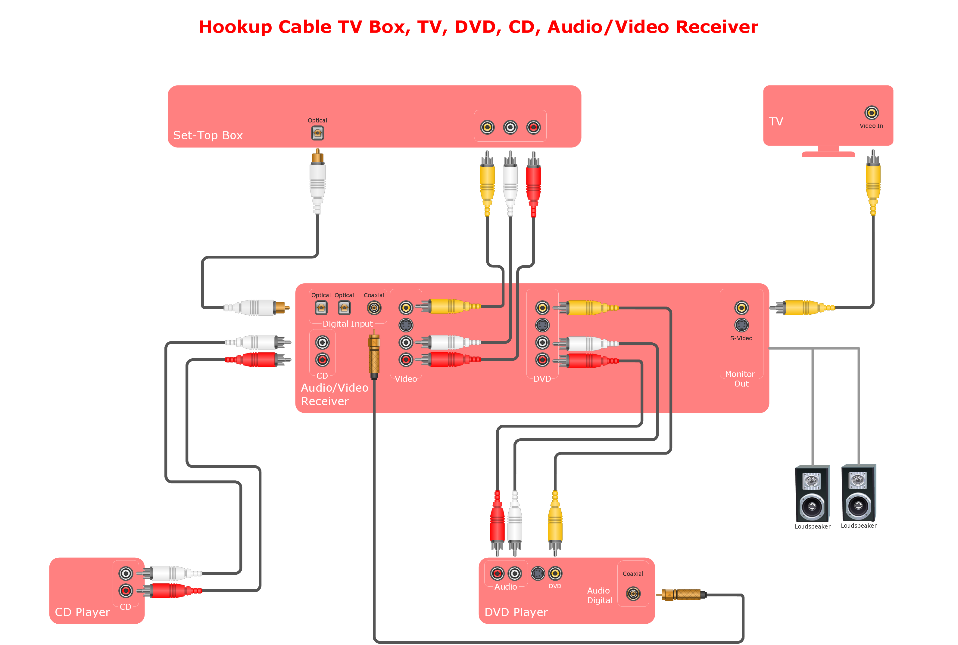
Network wiring cable. Computer and Network Examples

This example was created in ConceptDraw DIAGRAM using the Computer and Networks solution from the Computer and Networks area of ConceptDraw Solution Park.
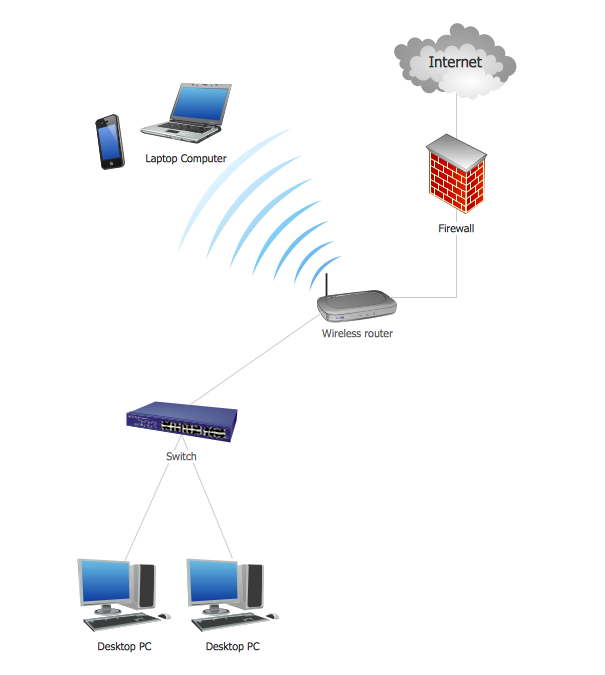
Local area network (LAN). Computer and Network Examples
 diagram")
ConceptDraw - Perfect Network Diagramming Software with examples of LAN Diagrams. ConceptDraw Network Diagram is ideal for network engineers and network designers who need to draw Local Area Network diagrams.
ConceptDraw DIAGRAM Network Diagram Tool


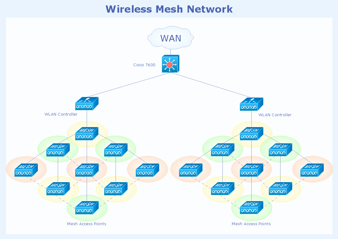
Network Topologies

Network Diagram Software Logical Network Diagram

This pinout diagram example showing a VGA connector (as viewed from the socket) was redesigned from the Wikimedia Commons file: DE15 Connector Pinout.svg. [commons.wikimedia.org/ wiki/ File:DE15_ Connector_ Pinout.svg]
"A Video Graphics Array (VGA) connector is a three-row 15-pin DE-15 connector. The 15-pin VGA connector is found on many video cards, computer monitors, and high definition television sets. On laptop computers or other small devices, a mini-VGA port is sometimes used in place of the full-sized VGA connector.
DE-15 is also conventionally called RGB connector, D-sub 15, mini sub D15, mini D15, DB-15, HDB-15, HD-15 or HD15 (High Density, to distinguish it from the older and less flexible DE-9 connector used on some older VGA cards, which has the same shell size but only two rows of pins).
VGA connectors and cables carry analog component RGBHV (red, green, blue, horizontal sync, vertical sync) video signals, and VESA Display Data Channel (VESA DDC) data. In the original version of DE-15 pinout, one pin was keyed by plugging the female connector hole; this prevented non-VGA 15 pin cables from being plugged into a VGA socket. Four pins carried Monitor ID bits which were rarely used; VESA DDC redefined some of these pins and replaced the key pin with +5 V DC power supply.
The VGA interface is not engineered to be hotpluggable (so that the user can connect or disconnect the output device while the host is running), although in practice this can be done and usually does not cause damage to the hardware or other problems. However, nothing in the design ensures that the ground pins make a connection first and break last, so hotplugging may introduce surges in signal lines which may or may not be adequately protected against. Also, depending on the hardware and software, detecting a monitor being connected might not work properly in all cases." [VGA connector. Wikipedia]
The pinout diagram example "VGA connector pinout" was created using the ConceptDraw PRO diagramming and vector drawing software extended with the Audio and Video Connectors solution from the Engineering area of ConceptDraw Solution Park.
VGA connector pinout

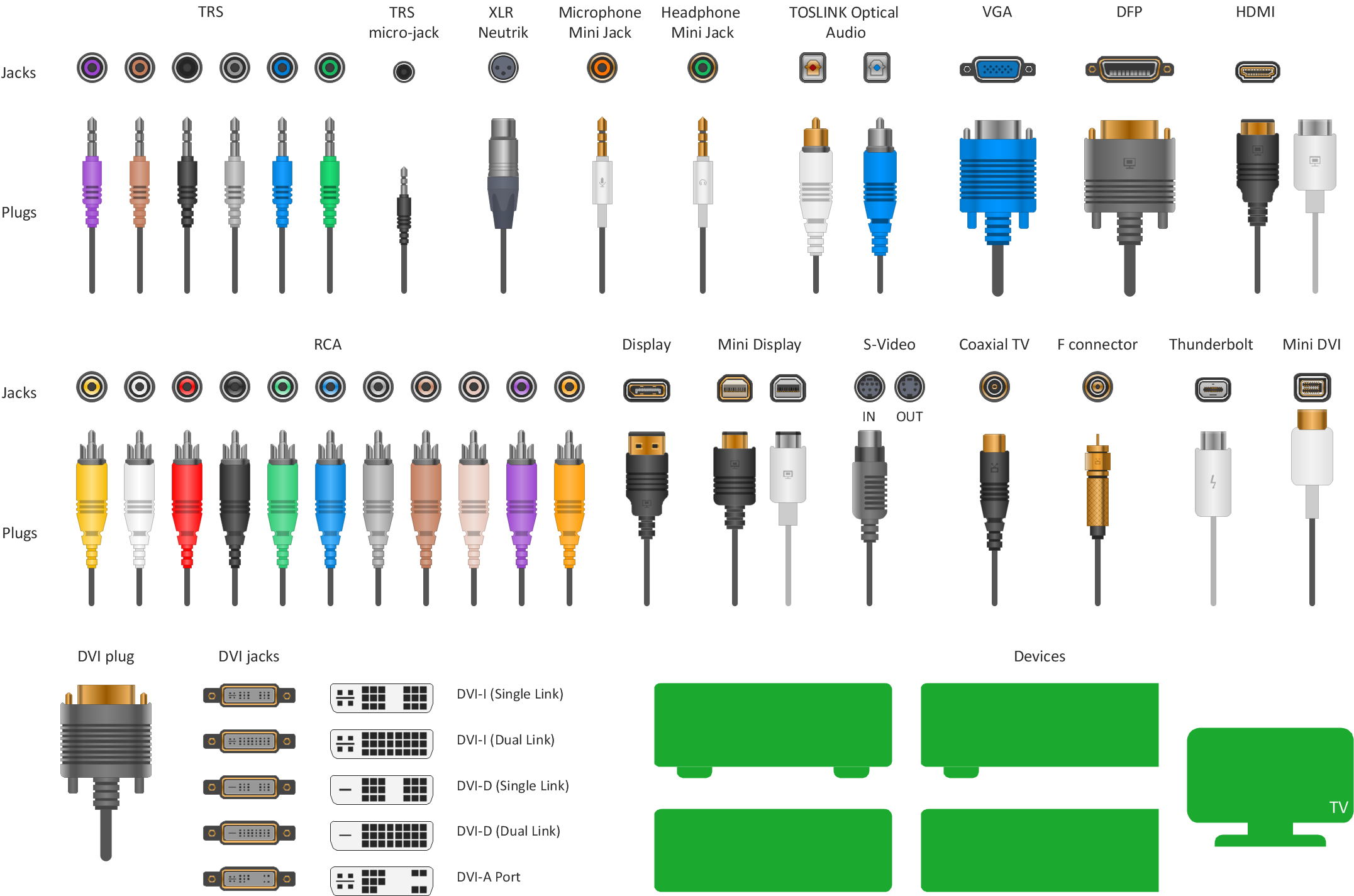
Audio and Video Connections Explained
Network Topology Illustration
Cisco Network Topology
Cisco Network Diagrams solution also provides 15 libraries of 508 Cisco symbols for network components and points, LAN and WAN, schematic and wiring drawings.
Standard Universal Audio & Video Connection Types
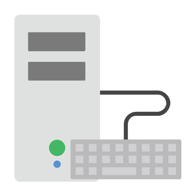
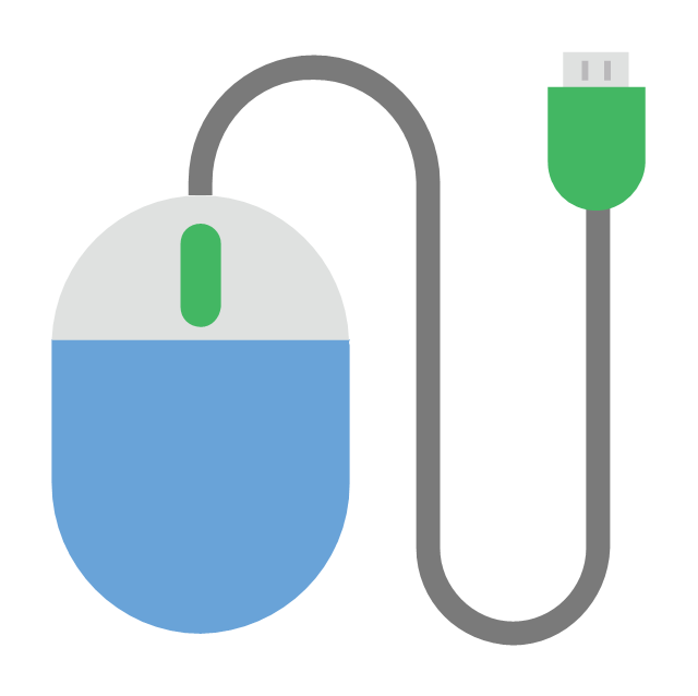
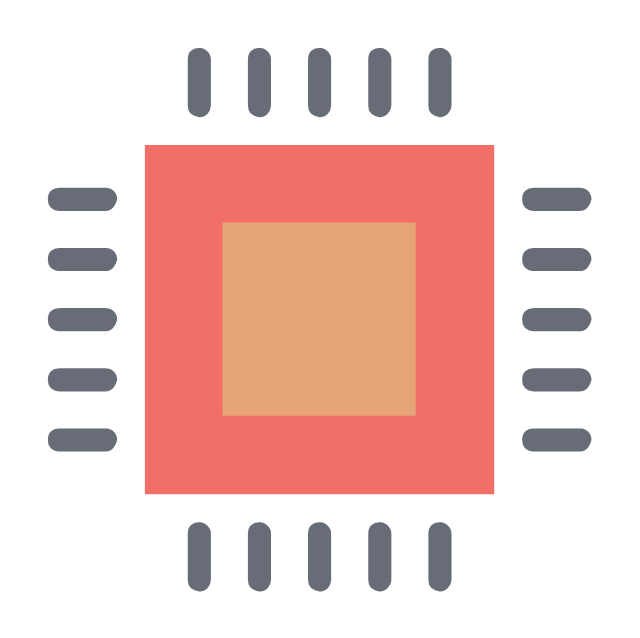
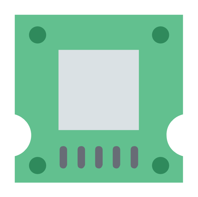
The vector stencils library "Hardware" contains 32 computer hardware and telecommunication equipment icons.
Use it to design your computing and telecom illustrations and infographics with ConceptDraw PRO diagramming and vector drawing software.
The vector stencils library "Hardware" is included in the Computers and Communications solution from the Illustration area of ConceptDraw Solution Park.
Use it to design your computing and telecom illustrations and infographics with ConceptDraw PRO diagramming and vector drawing software.
The vector stencils library "Hardware" is included in the Computers and Communications solution from the Illustration area of ConceptDraw Solution Park.
Rack

Workstation

Monitor with keyboard

Laptop

Laptop settings

Keyboard connection
Keyboard with mouse

Keyboard

USB computer mouse
WiFi mouse

Webcam

Remote control

Hard drive

Flash drive

Floppy

CPU
Hard drive
SD card
8GB memory card
Battery
Battery charging

Accumulator

Cable connector

Power socket
Power plug
USB cable
Electric bulb
Voltage meter
Speed control

Router
Modem
Bluetooth device

The vector stencils library "Network layout floorplan" contain 34 symbol icons for drawing computer network floor plans, communication equipment layouts, and structured cabling diagrams.
"Structured cabling is building or campus telecommunications cabling infrastructure that consists of a number of standardized smaller elements (hence structured) called subsystems. ...
Structured cabling design and installation is governed by a set of standards that specify wiring data centers, offices, and apartment buildings for data or voice communications using various kinds of cable, most commonly category 5e (CAT-5e), category 6 (CAT-6), and fibre optic cabling and modular connectors. These standards define how to lay the cabling in various topologies in order to meet the needs of the customer, typically using a central patch panel (which is normally 19 inch rack-mounted), from where each modular connection can be used as needed. Each outlet is then patched into a network switch (normally also rack-mounted) for network use or into an IP or PBX (private branch exchange) telephone system patch panel." [Structured cabling. Wikipedia]
The design elements example "Network layout floorplan - Vector stencils library" was created using the ConceptDraw PRO diagramming and vector drawing software extended with the Network Layout Floor Plans solution from the Computer and Networks area of ConceptDraw Solution Park.
PC

Scanner

Switch

Router

Modem

Hub

Rack Mount

Printer

Floor Mounted Outlet

Single Outlet

Duplex Outlet

Direct bus cable

Tops or bottoms bus cable

Side to side bus cable

Multi-tree bus cable

Bottom to side bus cable

Sides bus cable

Door

Door, threshold

Door, stop

Door, stop, threshold

Door, frame

Door, frame, threshold

Door, frame, stop

Door, frame, stop, threshold

Window

Window, sill

Window, sash

Window, sash, sill

Window, frame

Window, frame, sill

Window, frame, sash

Window, frame, sash, sill

Network Diagramming Software for Design Computer and Network Diagrams
_Win_Mac.png)
Network Diagramming with ConceptDraw DIAGRAM

- Cables And Connectors Of The Computer
- Audio Visual Cables and Connectors | Cable Network. Computer ...
- Cable Network. Computer and Network Examples | Network wiring ...
- Audio Visual Cables and Connectors | Standard Universal Audio ...
- Standard Universal Audio & Video Connection Types | Audio Visual ...
- Audio Visual Cables and Connectors | Standard Universal Audio ...
- Audio Visual Cables and Connectors | How to Make Audio and ...
- Computer Cables And Connectors Chart
- Standard Universal Audio & Video Connection Types | Audio Visual ...
- Diagram Of Different Network Cable And Connectors
- Audio Visual Cables and Connectors | Design elements - Audio and ...
- Audio Visual Connectors Types | Network Glossary Definition ...
- Types Of Cables Connectors
- Network wiring cable . Computer and Network Examples | Network ...
- Diagram Of Cable Connection
- Electrical Symbols — Terminals and Connectors | Network wiring ...
- Terminals and connectors - Vector stencils library | Network wiring ...
- Cable Network. Computer and Network Examples | Local area ...
- How To use House Electrical Plan Software | Network wiring cable ...
- Audio Visual Cables and Connectors | ConceptDraw Arrows10 ...
- ERD | Entity Relationship Diagrams, ERD Software for Mac and Win
- Flowchart | Basic Flowchart Symbols and Meaning
- Flowchart | Flowchart Design - Symbols, Shapes, Stencils and Icons
- Flowchart | Flow Chart Symbols
- Electrical | Electrical Drawing - Wiring and Circuits Schematics
- Flowchart | Common Flowchart Symbols
- Flowchart | Common Flowchart Symbols