Booch OOD Diagram

OMT Method

All diagrams produced with ConceptDraw DIAGRAM are vector graphic documents and are available for reviewing, modifying, and converting to a variety of formats (image, HTML, PDF file, MS PowerPoint Presentation, Adobe Flash or MS Visio XML).
Object-Oriented Development (OOD) Method

This sample was created in ConceptDraw DIAGRAM diagramming and vector drawing software using the Rapid UML Solution from the Software Development area of ConceptDraw Solution Park.
Critical Path Method in ConceptDraw PROJECT
COM and OLE Diagram

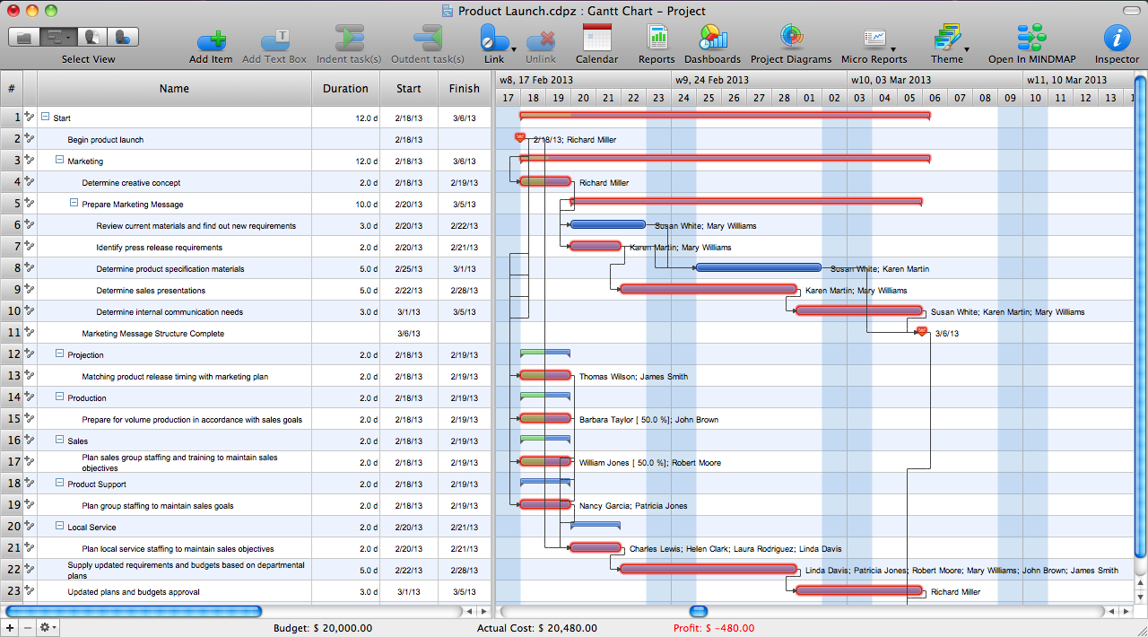
What is Gantt Chart (historical reference)

SysML Diagram
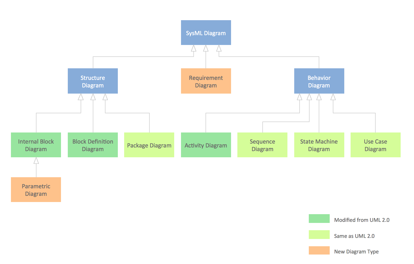
Model Based Systems Engineering

Program Structure Diagram
Software Diagrams

ConceptDraw DIAGRAM is a perfect tool for Designing and planning tasks; Developing Visualization Solutions; Project Planning (Gantt Charts, Timelines, Project Schedules).
Garrett IA Diagrams with ConceptDraw DIAGRAM

About UML

This sample shows the work of the taxi service and is used by taxi stations, by airports, in the tourism field and delivery service.
Martin ERD Diagram

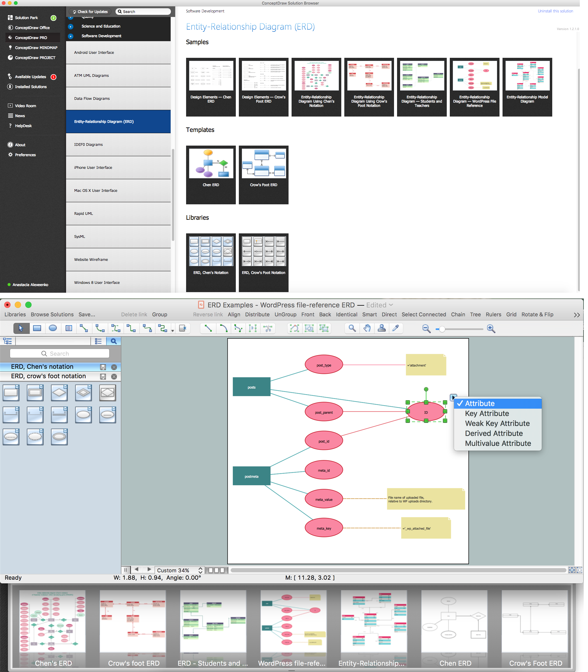
ER Diagram Programs for Mac
Structured Systems Analysis and Design Method (SSADM) with ConceptDraw DIAGRAM

- Object-Oriented Development (OOD) Method | Booch OOD Diagram ...
- Booch OOD Diagram | Object-Oriented Development (OOD) Method ...
- Booch OOD Diagram | Examples Of Omt Methodology
- Booch OOD Diagram | Examples for OOSE Method | OMT Method ...
- Booch OOD Diagram | Examples for OOSE Method | UML Flowchart ...
- Booch OOD Diagram | Examples for OOSE Method | OOSE Method ...
- Examples for OOSE Method | OOSE Method | Booch OOD Diagram ...
- Booch OOD Diagram | Examples for OOSE Method | Online Diagram ...
- PM Agile | Workflow Diagram Template | Booch OOD Diagram ...
- Booch OOD Diagram | Program Structure Diagram | OMT Method ...
- Booch OOD Diagram | OOSE Method | About UML | Object Oriented ...
- OMT Method | Booch OOD Diagram | State Machine Diagram | Omt ...
- Directional control valve | Booch OOD Diagram | Interior Design ...
- Examples for OOSE Method | OOSE Method | Object-Oriented ...
- Booch OOD Diagram | Yourdon and Coad Diagram | Software ...
- Booch OOD Diagram | Express-G Diagram | Gane Sarson Diagram ...
- Object-Oriented Development (OOD) Method | UML Diagram | About ...
- Structured Systems Analysis and Design Method (SSADM) with ...
- Booch OOD Diagram | What is Gantt Chart (historical reference ...
- Object-Oriented Design | Booch OOD Diagram | Coad/Yourdon's ...
- ERD | Entity Relationship Diagrams, ERD Software for Mac and Win
- Flowchart | Basic Flowchart Symbols and Meaning
- Flowchart | Flowchart Design - Symbols, Shapes, Stencils and Icons
- Flowchart | Flow Chart Symbols
- Electrical | Electrical Drawing - Wiring and Circuits Schematics
- Flowchart | Common Flowchart Symbols
- Flowchart | Common Flowchart Symbols