Process Flowchart


Structured Systems Analysis and Design Method (SSADM) with ConceptDraw PRO

Types of Flowcharts


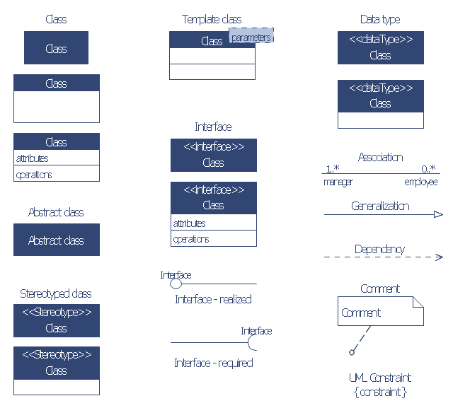
The vector stencils library "Bank UML class diagram" contains 19 shapes for drawing UML class diagrams.
Use it for object-oriented modeling of your bank information system.
"The class diagram is the main building block of object oriented modelling. It is used both for general conceptual modelling of the systematics of the application, and for detailed modelling translating the models into programming code. Class diagrams can also be used for data modeling. The classes in a class diagram represent both the main objects, interactions in the application and the classes to be programmed.
In the diagram, classes are represented with boxes which contain three parts:
* The top part contains the name of the class. It is printed in bold and centered, and the first letter is capitalized.
* The middle part contains the attributes of the class. They are left-aligned and the first letter is lowercase.
* The bottom part contains the methods the class can execute. They are also left-aligned and the first letter is lowercase.
In the design of a system, a number of classes are identified and grouped together in a class diagram which helps to determine the static relations between those objects. With detailed modelling, the classes of the conceptual design are often split into a number of subclasses." [Class diagram. Wikipedia]
This example of UML class diagram symbols for the ConceptDraw PRO diagramming and vector drawing software is included in the ATM UML Diagrams solution from the Software Development area of ConceptDraw Solution Park.
UML class diagram symbols
 IDEF0 Diagrams
IDEF0 Diagrams visualize system models using the Integration Definition for Function Modeling (IDEF) methodology. Use them for analysis, development and integration of information and software systems, and business process modelling.
HelpDesk
How to Draw a Block Diagram in ConceptDraw PRO

HelpDesk
How To Convert a Block Diagram to Adobe PDF

 Pyramid Diagrams
Pyramid Diagrams solution extends ConceptDraw PRO software with templates, samples and library of vector stencils for drawing the marketing pyramid diagrams.
 SYSML
SYSML
The SysML solution helps to present diagrams using Systems Modeling Language; a perfect tool for system engineering.
IDEF0 standard with ConceptDraw PRO

According to the IDEF0 standard any process can be described in the form of a block (Activity Box) which has inputs and outputs. The process consists in transformation of inputs into outputs under the influence of the management and in the presence of necessary resources. Outputs of the given process later on can be either inputs for the next process or resources, or management means.
IDEF0 Diagram

- 4 Level pyramid model diagram - Information systems types | 5 Level ...
- Chart Of Management Information System With Diagram
- 4 Level pyramid model diagram - Information systems types ...
- UML Diagram Types List | Block diagram - Types of individual ...
- Pyramid Diagram | Design elements - Technology | Process ...
- Element Of Information Systems With Diagram
- 4 Level pyramid model diagram - Information systems types ...
- UML Deployment Diagram. Design Elements | Block diagram ...
- Software Development | Information Architecture | What Is ...
- Explain Developing Information System With Diagram
- DFD Library System | Data Flow Diagram Symbols. DFD Library ...
- Pyramid Diagram | Pyramid Chart Examples | Block diagram - Five ...
- Block Diagram Of Finacl Mangement Information
- Business Support System Block Diagram
- 4 Level pyramid model diagram - Information systems types | Types ...
- UML Block Diagram | UML Collaboration Diagram. Design Elements ...
- Element Of System In System Analysis Design With Diagram
- How to Create Flowcharts for an Accounting Information System ...
- Block Diagram For Business Support System
- Process Flowchart | Bank System | Design elements - Bank UML ...
- ERD | Entity Relationship Diagrams, ERD Software for Mac and Win
- Flowchart | Basic Flowchart Symbols and Meaning
- Flowchart | Flowchart Design - Symbols, Shapes, Stencils and Icons
- Flowchart | Flow Chart Symbols
- Electrical | Electrical Drawing - Wiring and Circuits Schematics
- Flowchart | Common Flowchart Symbols
- Flowchart | Common Flowchart Symbols