Building Drawing. Design Element: Piping Plan


Building Drawing Software for Design Piping Plan

Building Drawing Software for Designing Plumbing

Building Drawing. Design Element — Plumbing

Interior Design. Piping Plan — Design Elements

Building Drawing Software for Design Office Layout Plan

Its Cubicles and Work Surfaces library consists of 46 objects, Office Equipment library consists of 33 objects including accessories and electronics, Office Furniture library has all 36 objects that can be found in Office Layout Plans solution any time, even right now. Check it out! Design your office and fill its space with what you want using pre-made layouts. Start now not to waste your time looking for some other software. Find 1493 vector stencils in 49 libraries in ConceptDraw DIAGRAM and use anyone you like!
Drawing Illustration

 Plumbing and Piping Plans
Plumbing and Piping Plans solution extends ConceptDraw DIAGRAM.2.2 software with samples, templates and libraries of pipes, plumbing, and valves design elements for developing of water and plumbing systems, and for drawing Plumbing plan, Piping plan, PVC Pipe plan, PVC Pipe furniture plan, Plumbing layout plan, Plumbing floor plan, Half pipe plans, Pipe bender plans.
Piping and Instrumentation Diagram Software

Plumbing and Piping Plans solution helps you create quick and easy: key piping and instrument details ,piping diagrams, instrumentation diagrams, schemes of hot and cold water supply systems, control and shutdown schemes, diagrams of plumbing systems, heating schemes, schematics of waste water disposal systems, safety and regulatory requirements, diagrams of ventilation systems, mechanical diagrams, industrial diagrams, basic start up and operational information.
Pipe Bender Plans

Half Pipe Plans

Building Plans with ConceptDraw DIAGRAM

The vector stencils libraries "Pipes 1" and "Pipes 2" contain 28 and 48 pipe, tubing and fitting symbols, respectively.
"Pipe is hollow cylinder used to conduct or transfer fluids (liquids and gases) from one place to other place. The main difference between pipe and tube is the critical dimension used to describe the pipe size or the tube size. For pipe, internal diameter (ID) roughly corresponds to the nominal pipe size for standard wall thickness. For tube, the outer diameter (OD) closely corresponds to the tube size. In current European standards pipes and tubes are nowadays described as outside diameter by wall thickness. The three standard types of pipe ends used in the piping industriesare; Plain Ends (PE), Threaded Ends (TE) and Beveled Ends (BE). In the past, many types of material have been used in conveying water from one point to another. Masonry and wood were probably the first materials used. Plastics are the newest, and are now being used quite extensively." [Piping. Wikipedia]
Use the design elements libraries "Pipes 1" and "Pipes 2" for drawing plumbing and piping building plans, schematic diagrams, blueprints, or technical drawings of waste water disposal systems, hot and cold water supply systems using the ConceptDraw PRO diagramming and vector drawing software.
The shapes libraries "Pipes 1" and "Pipes 2" are contained in the Plumbing and Piping Plans solution from the Building Plans area of ConceptDraw Solution Park.
Piping symbols
.png--diagram-flowchart-example.png)
The vector stencils libraries "Pipes 1" and "Pipes 2" contain 28 and 48 pipe, tubing and fitting symbols, respectively.
"A fitting is used in pipe plumbing systems to connect straight pipe or tubing sections, to adapt to different sizes or shapes, and for other purposes, such as regulating or measuring fluid flow. The term plumbing is generally used to describe conveyance of water, gas, or liquid waste in ordinary domestic or commercial environments, whereas piping is often used to describe high-performance (e.g. high pressure, high flow, high temperature, hazardous materials) conveyance of fluids in specialized applications. The term tubing is sometimes used for lighter-weight piping, especially types that are flexible enough to be supplied in coiled form.
Fittings (especially uncommon types) require money, time, materials, and tools to install, so they are a non-trivial part of piping and plumbing systems." [Piping and plumbing fitting. Wikipedia]
Use the design elements libraries "Pipes 1" and "Pipes 2" for drawing plumbing and piping building plans, schematic diagrams, blueprints, or technical drawings of waste water disposal systems, hot and cold water supply systems using the ConceptDraw PRO diagramming and vector drawing software.
The shapes libraries "Pipes 1" and "Pipes 2" are contained in the Plumbing and Piping Plans solution from the Building Plans area of ConceptDraw Solution Park.
Piping symbols
.png--diagram-flowchart-example.png)
HelpDesk
How to Create a Residential Plumbing Plan

Interior Design. Plumbing — Design Elements

Building Drawing. Design Element Site Plan

Use Site Plan symbols to draw your own residential and commercial landscape design, parks planning, yard layouts, plat maps, outdoor recreational facilities, and irrigation systems.
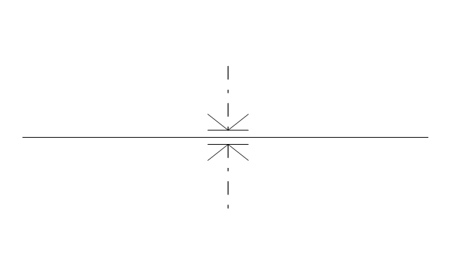
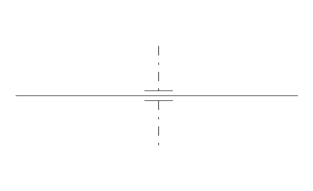
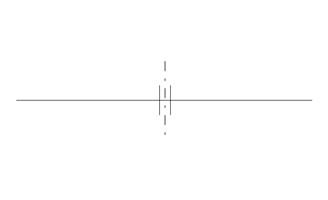
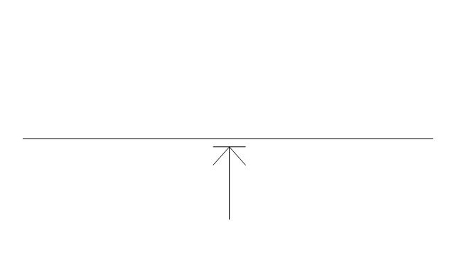
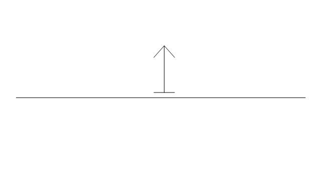
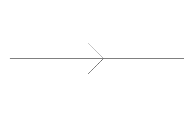
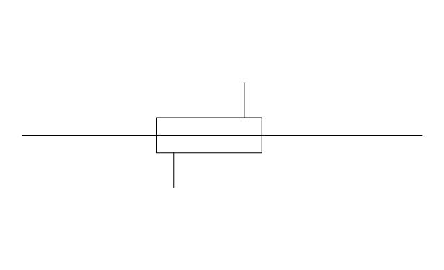
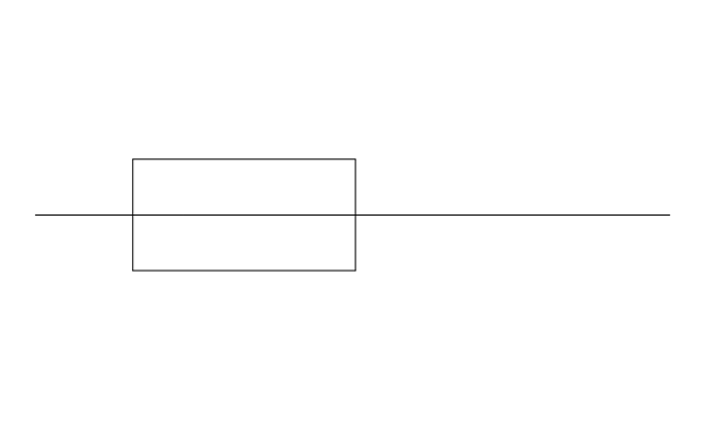
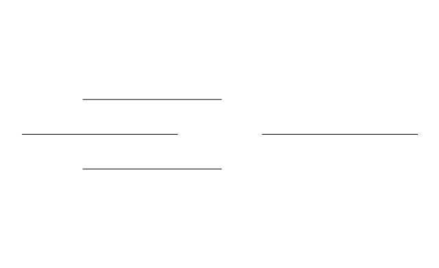
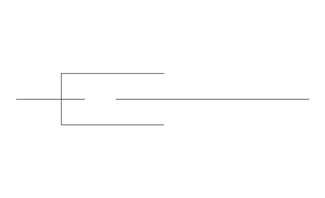
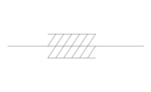
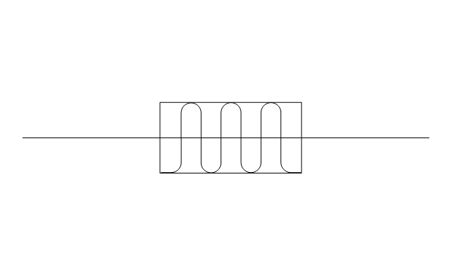
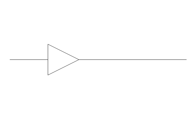
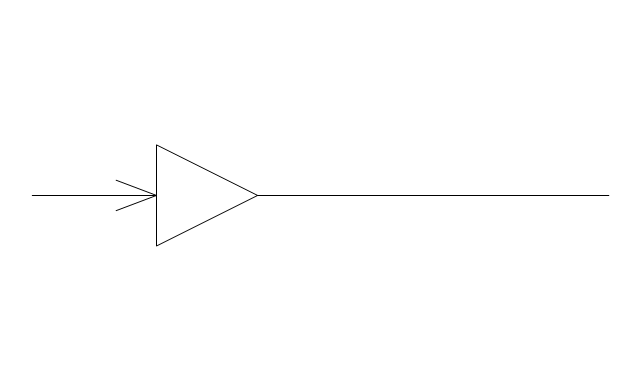
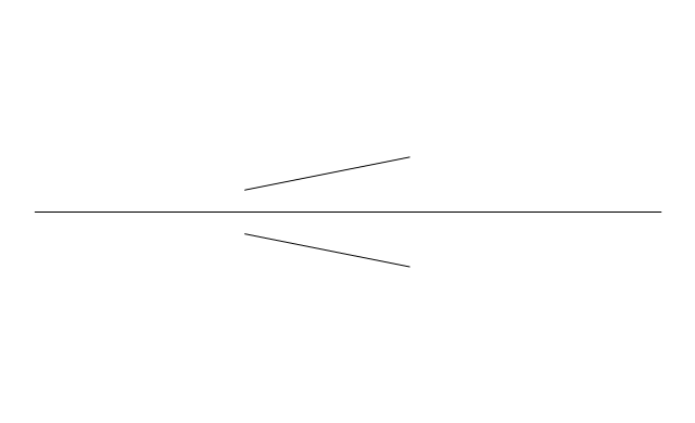
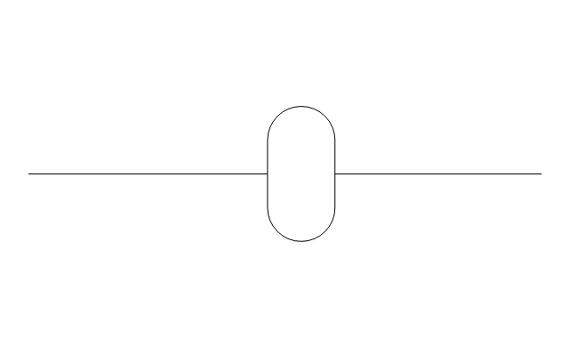
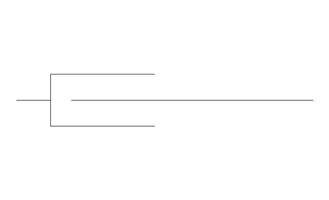
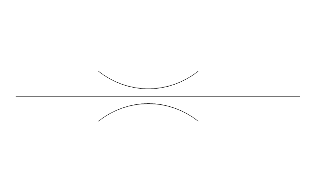
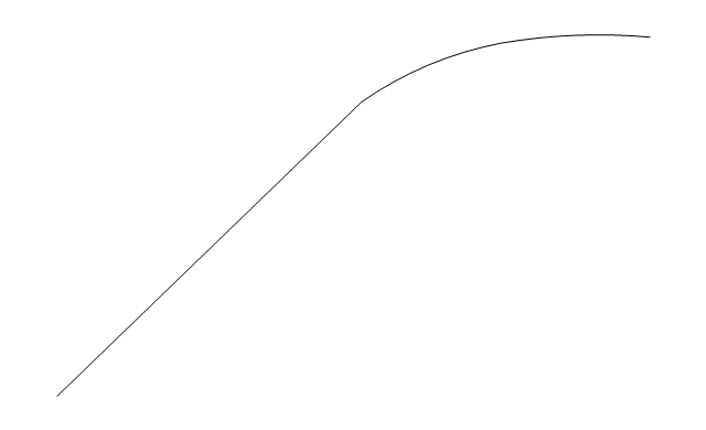
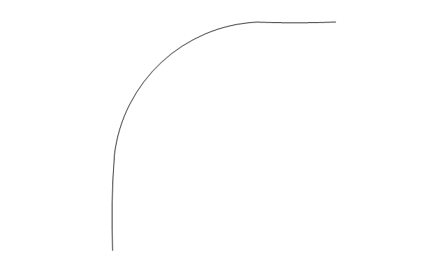
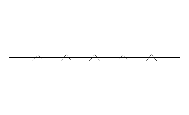
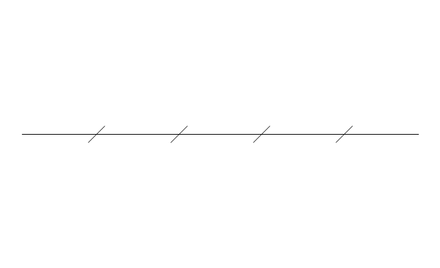
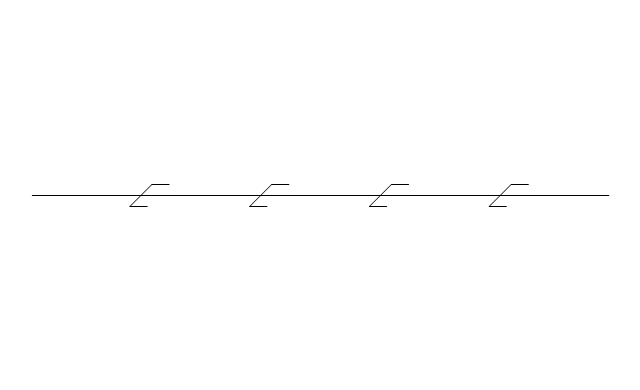
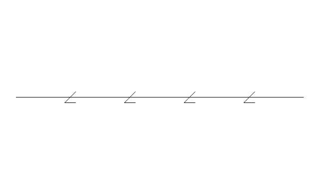
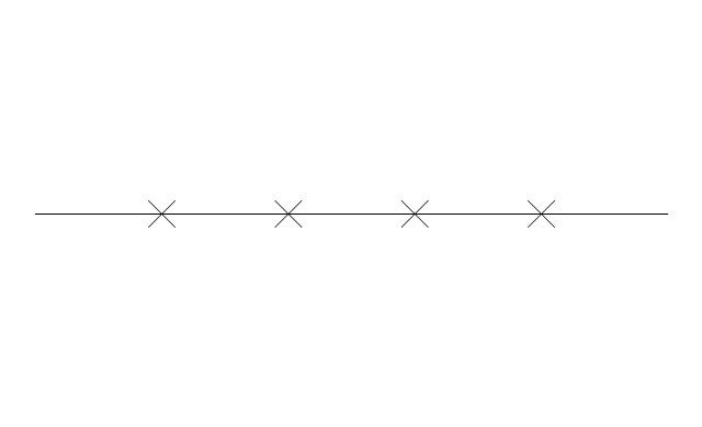
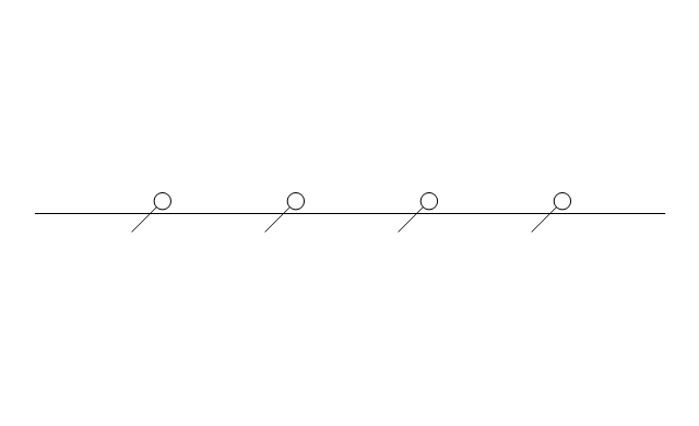
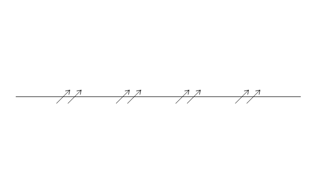
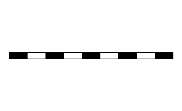
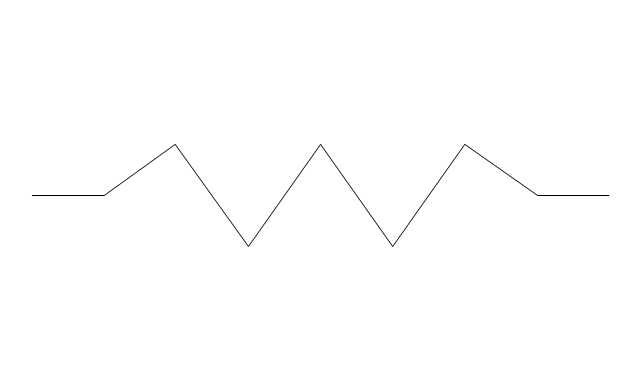
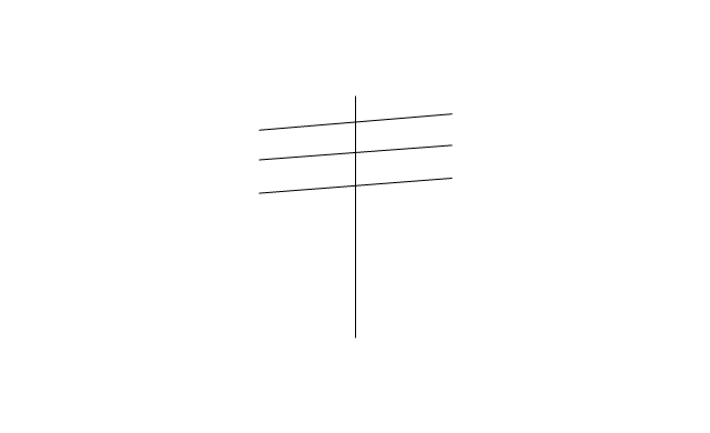
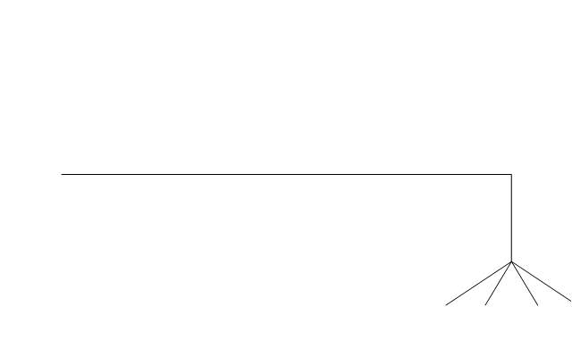
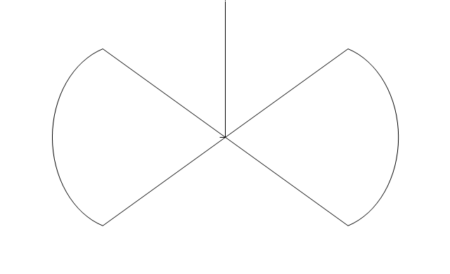
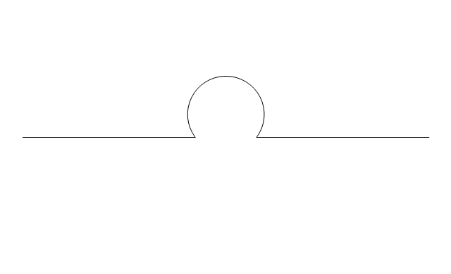
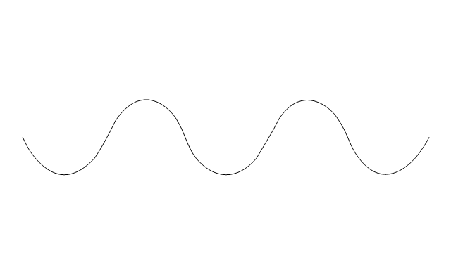
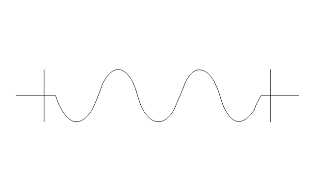
The vector stencils library "Pipes 2" contains 48 symbols of pipes. Use it for drawing plumbing and piping building plans, schematic diagrams, blueprints, or technical drawings of waste water disposal systems, hot and cold water supply systems in the ConceptDraw PRO diagramming and vector drawing software extended with the Plumbing and Piping Plans solution from the Building Plans area of ConceptDraw Solution Park.
Crossing
Junction
Basic support
Guide 1
Guide 2
Guide 3
Stopper
Anchor
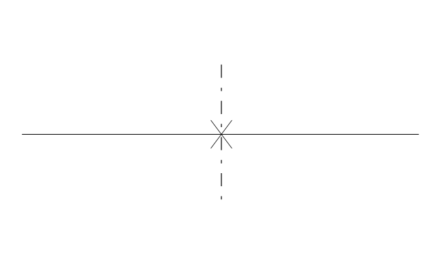
Support / anchor
Hunger
Cross
Double branch

Jacketed
Sleeved
Sleeve joint
Expansion sleeve joint
Lagged
Bellows
Flow indication
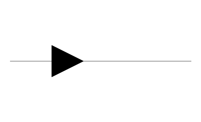
Flow indication 2
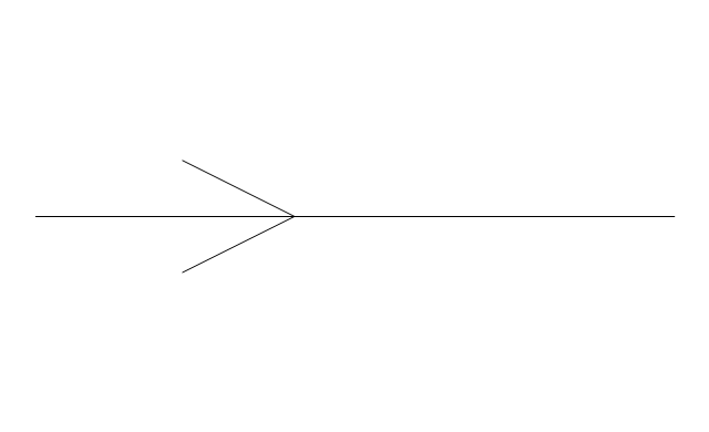
Reducer
Reducer,arrow
Pipe bore change
Flexibility provision
Sleeve extension
Flow restrictor
Elbow 45
Elbow 90
Heated or cooled

Pneumatic line
Signal line
Electric line
Hydraulic line
Capillary line
Internal connection
Route radiation
Mechanical linkage
Electrical device
Vibratory device
Weight device
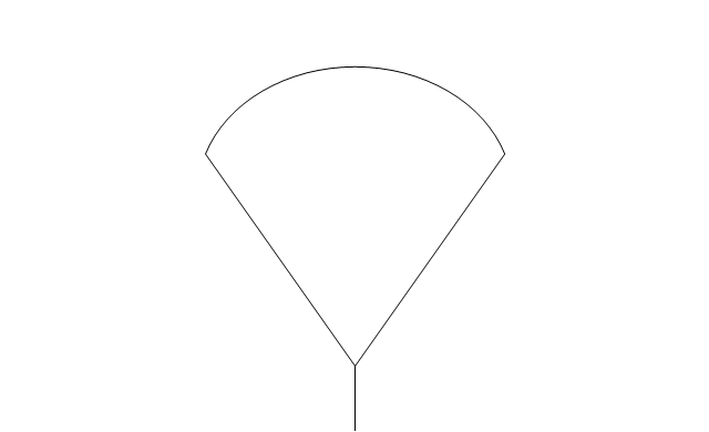
Spray device
Rotary motion
Stirring / fan
Access points

Trap

Expansion loop
Flexible hose
Flexible hose, flanged
CAD Software for Architectural Designs

ConceptDraw DIAGRAM diagramming and vector drawing software allows you the possibility to draw your architectural designs quick, simple and effective.
Use the libraries with a set of vector objects, templates and samples from the Floor Plans Solution from the Building Plans area of ConceptDraw Solution Park for designing your professional architectural designs.
How To use Building Plan Examples

- Building Drawing . Design Element: Piping Plan | Plumbing and ...
- Plumbing and Piping Plans | Bilding Droing
- Piping and Instrumentation Diagram Software | Building Drawing ...
- How to Create a Residential Plumbing Plan | Plumbing and Piping ...
- Plumbing and Piping Plans | How to Create a Residential Plumbing ...
- Plumbing and Piping Plans | Bilding
- Online Pipe Drawing For Mac
- Design elements - Pipes
- Building Drawing Software for Designing Plumbing | Piping and ...
- Building Drawing . Design Element: Piping Plan | Electrical Design ...
- Building Drawing . Design Element: Piping Plan | Piping and ...
- Plumbing and Piping Plans | Design elements - Pipes (part 1 ...
- Plumbing and Piping Plans | Plant Layout Plans | Plumbing Layout ...
- Building Drawing Software for Design Piping Plan | Interior Design ...
- Plumbing and Piping Plans | Home floor plan template | Layout Plan ...
- Design elements - Pipes (part 1) | Welding symbols | Pipes 2 ...
- Plumbing and Piping Plans | Piping Drawing Basic Symbol Power ...
- Plumbing and Piping Plans | Water Supply Layout Plan
- Plumbing and Piping Plans | Plumbing Design Software Free ...
- Plumbing and Piping Plans | Building Plan Mechanical Fittings ...
- ERD | Entity Relationship Diagrams, ERD Software for Mac and Win
- Flowchart | Basic Flowchart Symbols and Meaning
- Flowchart | Flowchart Design - Symbols, Shapes, Stencils and Icons
- Flowchart | Flow Chart Symbols
- Electrical | Electrical Drawing - Wiring and Circuits Schematics
- Flowchart | Common Flowchart Symbols
- Flowchart | Common Flowchart Symbols