This AV connector pinout diagram example was redesigned from the file: DVI pinout.svg. [en.wikipedia.org/ wiki/ File:DVI_ pinout.svg]
"In electronics, a pinout (sometimes written "pin-out") is a cross-reference between the contacts, or pins, of an electrical connector or electronic component, and their functions. ...
The functions of contacts in electrical connectors, be they power- or signaling-related, must be specified in order for connectors to be interchangeable. When connected, each contact of a connector must mate with the contact on the other connector that has the same function. If contacts of disparate functions are allowed to make contact, the connection may fail and damage may result. Therefore, pinouts are a vital reference when building and testing connectors, cables, and adapters." [Pinout. Wikipedia]
The example "DVI pinout diagram" was created using the ConceptDraw PRO diagramming and vector drawing software extended with the Audio and Video Connectors solution from the Engineering area of ConceptDraw Solution Park.
A female DVI-I socket from the front

Electrical Symbols — Terminals and Connectors

26 libraries of the Electrical Engineering Solution of ConceptDraw DIAGRAM make your electrical diagramming simple, efficient, and effective. You can simply and quickly drop the ready-to-use objects from libraries into your document to create the electrical diagram.
Wiring Diagrams with ConceptDraw DIAGRAM

Audio and Video Interfaces and Connectors
Audio and Video Connections Explained
 Audio and Video Connectors
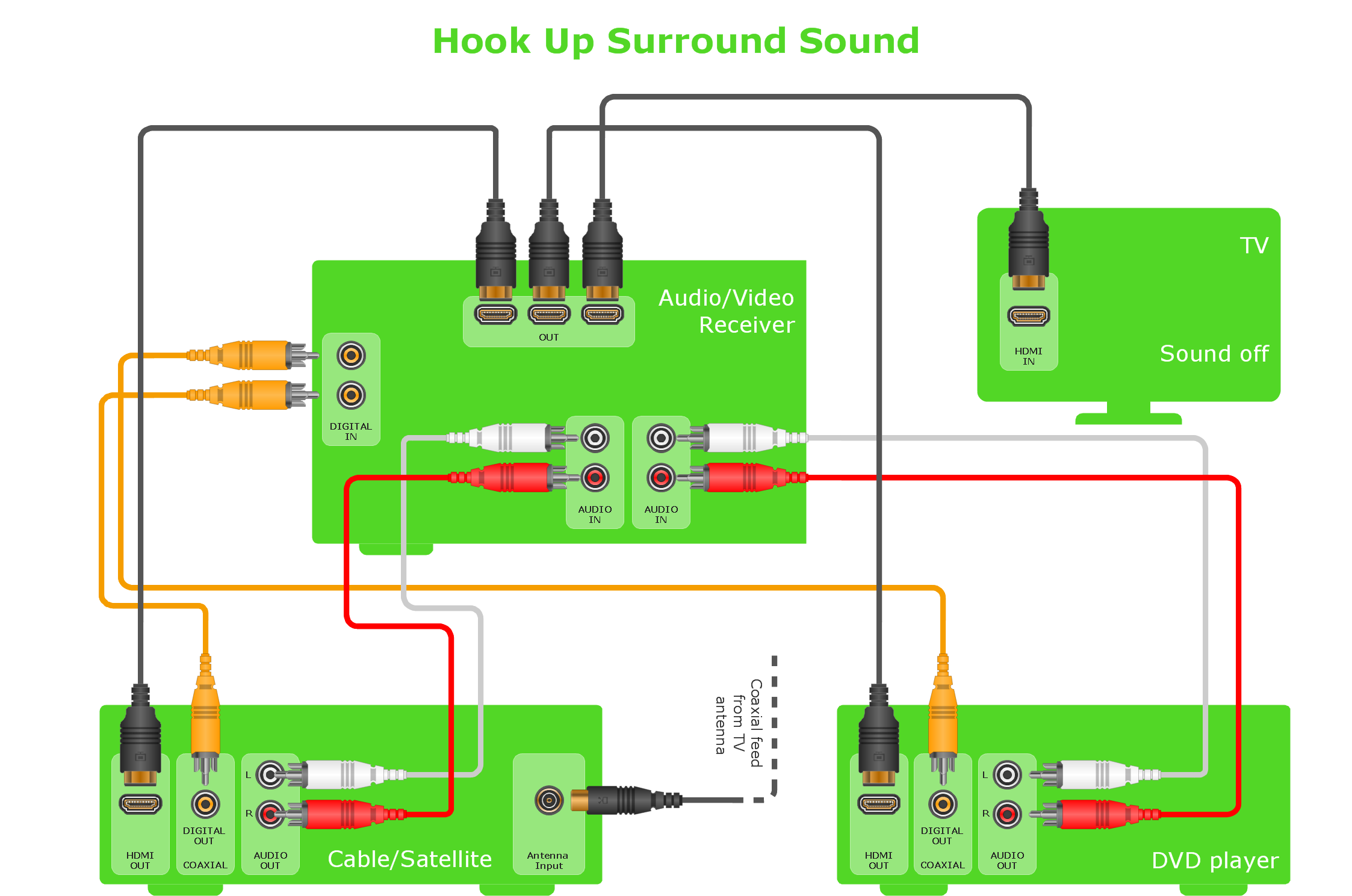
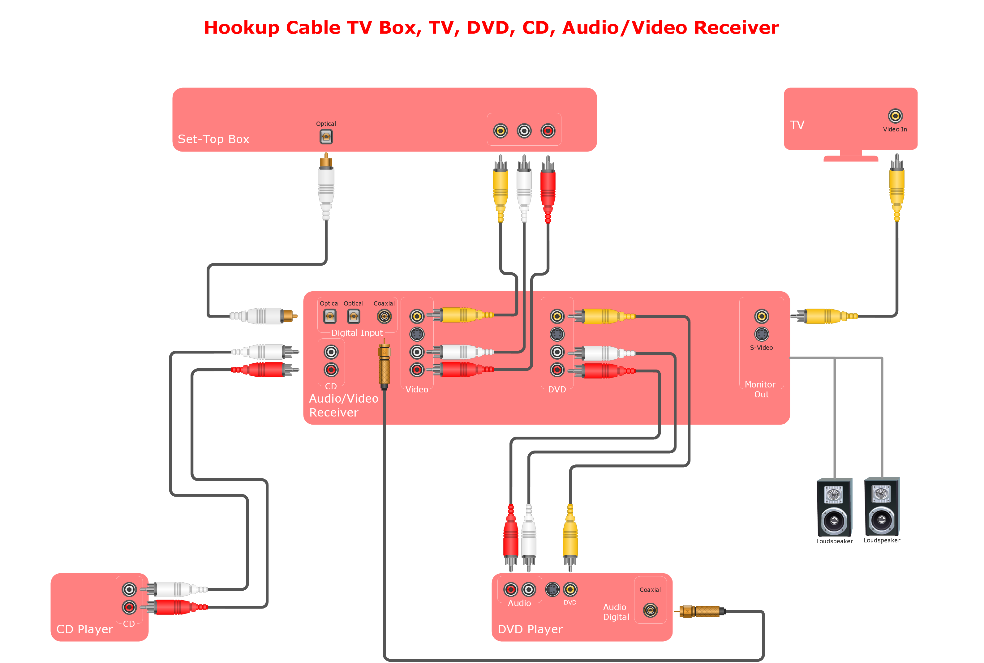
Audio and video connectors solution extends ConceptDraw DIAGRAM software with templates, samples and library of vector stencils for drawing audio and video hook up diagrams.
- Av Socket Diagram In A Circuit
- DVI pinout diagram | DVI connector types | Dvi To Av Pinout Wiring
- Audio & Video Connector Types | DVI pinout diagram | Wiring ...
- Wiring Diagrams with ConceptDraw PRO | Audio & Video Connector ...
- Av Connection Diagrams
- DVI pinout diagram | VGA connector pinout | Wiring Diagrams with ...
- Dvi To Av Circuit
- Audio & Video Connector Types | DVI connector types | Audio and ...
- Av Diagram Software
- Av Cable Diagram
- DVI pinout diagram
- Technical Diagram Of Av Solution
- VGA connector pinout | DVI connector types | DVI pinout diagram ...
- VGA connector pinout | DVI pinout diagram | Wiring Diagrams with ...
- VGA connector pinout | DVI pinout diagram | Audio Video ...
- DVI pinout diagram | Dvi Cable Pin Connections
- Audio Visual Connectors Types | S Video Connection | Audio Video ...
- Standard Universal Audio & Video Connection Types | Audio and ...
- How To use House Electrical Plan Software | DVI pinout diagram ...
- Application - Vector stencils library | VGA connector pinout ...
- ERD | Entity Relationship Diagrams, ERD Software for Mac and Win
- Flowchart | Basic Flowchart Symbols and Meaning
- Flowchart | Flowchart Design - Symbols, Shapes, Stencils and Icons
- Flowchart | Flow Chart Symbols
- Electrical | Electrical Drawing - Wiring and Circuits Schematics
- Flowchart | Common Flowchart Symbols
- Flowchart | Common Flowchart Symbols