The vector stencils library "Soccer (Football) positions" contains 18 symbols for drawing association football (soccer) positions diagram.
"In the sport of association football, each of the eleven players on a team is assigned to a particular position on the field of play. A team is made up of one goalkeeper and ten outfield players who fill various defensive, midfield and attacking positions depending on the formation deployed. These positions describe both the player's main role and their area of operation on the pitch." [Association football positions. Wikipedia]
The symbols example "Design elements - Soccer (Football) positions" was created using the ConceptDraw PRO diagramming and vector drawing software extended with the Soccer solution from the Sport area of ConceptDraw Solution Park.
www.conceptdraw.com/ solution-park/ sport-soccer
Association football (soccer) position symbols
-position-symbols-design-elements---soccer-(football)-positions.png--diagram-flowchart-example.png)
The vector stencils library "UML class diagrams" contains 38 symbols for the ConceptDraw PRO diagramming and vector drawing software.
"... classes are represented with boxes which contain three parts:
(1) The top part contains the name of the class. It is printed in Bold, centered and the first letter capitalized.
(2) The middle part contains the attributes of the class. They are left aligned and the first letter is lower case.
(3) The bottom part gives the methods or operations the class can take or undertake. They are also left aligned and the first letter is lower case. ...
To indicate a classifier scope for a member, its name must be underlined. ...
An association can be named, and the ends of an association can be adorned with role names, ownership indicators, multiplicity, visibility, and other properties. ...
Aggregation ... is graphically represented as a hollow diamond shape on the containing class end of the tree with a single line that connects the contained class to the containing class.
... graphical representation of a composition relationship is a filled diamond shape on the containing class end of the tree of lines that connect contained class(es) to the containing class.
... graphical representation of a Generalization is a hollow triangle shape on the superclass end of the line (or tree of lines) that connects it to one or more subtypes.
... graphical representation of a Realization is a hollow triangle shape on the interface end of the dashed line (or tree of lines) that connects it to one or more implementers. A plain arrow head is used on the interface end of the dashed line that connects it to its users.
Multiplicity ... representation of an association is a line with an optional arrowhead indicating the role of the object(s) in the relationship, and an optional notation at each end indicating the multiplicity of instances of that entity (the number of objects that participate in the association).
Entity classes ... are drawn as circles with a short line attached to the bottom of the circle. Alternatively, they can be drawn as normal classes with the «entity» stereotype notation above the class name." [Class diagram. Wikipedia]
The example "Design elements - UML class diagrams" is included in the Rapid UML solution from the Software Development area of ConceptDraw Solution Park.
UML class diagram symbols

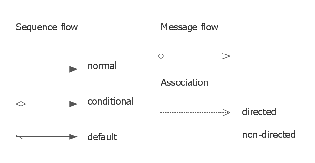
The vector stencils library "Connections BPMN1.2" contains 6 connection symbols of sequence flow, message flow, and association.
Use these shapes for drawing business process diagrams (BPMN 1.2) using the ConceptDraw PRO diagramming and vector drawing software.
"Connections.
Flow objects are connected to each other using Connecting objects, which are of three types: sequences, messages, and associations.
(1) Sequence Flow.
A Sequence Flow is represented with a solid line and arrowhead, and shows in which order the activities are performed. The sequence flow may also have a symbol at its start, a small diamond indicates one of a number of conditional flows from an activity, while a diagonal slash indicates the default flow from a decision or activity with conditional flows.
(2) Message Flow.
A Message Flow is represented with a dashed line, an open circle at the start, and an open arrowhead at the end. It tells us what messages flow across organizational boundaries (i.e., between pools). A message flow can never be used to connect activities or events within the same pool.
(3) Association.
An Association is represented with a dotted line. It is used to associate an Artifact or text to a Flow Object, and can indicate some directionality using an open arrowhead (toward the artifact to represent a result, from the artifact to represent an input, and both to indicate it is read and updated). No directionality is used when the Artifact or text is associated with a sequence or message flow (as that flow already shows the direction)." [Business Process Model and Notation. Wikipedia]
The example "Design elements - Connections BPMN1.2" is included in the Business Process Diagram solution from the Business Processes area of ConceptDraw Solution Park.
BPMN1.2 connection symbols
The vector stencils library "UML use case diagrams" contains 25 symbols for the ConceptDraw PRO diagramming and vector drawing software.
"Use case diagrams are usually referred to as behavior diagrams used to describe a set of actions (use cases) that some system or systems (subject) should or can perform in collaboration with one or more external users of the system (actors). Each use case should provide some observable and valuable result to the actors or other stakeholders of the system. ...
Use case diagrams are in fact twofold - they are both behavior diagrams, because they describe behavior of the system, and they are also structure diagrams - as a special case of class diagrams where classifiers are restricted to be either actors or use cases related to each other with associations. ...
Use case is usually shown as an ellipse containing the name of the use case. ...
Name of the use case could also be placed below the ellipse. ...
If a subject (or system boundary) is displayed, the use case ellipse is visually located inside the system boundary rectangle. Note, that this does not necessarily mean that the subject classifier owns the contained use cases, but merely that the use case applies to that classifier. ...
A list of use case properties - operations and attributes - could be shown in a compartment within the use case oval below the use case name. ...
Use case with extension points may be listed in a compartment of the use case with the heading extension points. ...
A use case can also be shown using the standard rectangle notation for classifiers with an ellipse icon in the upper right-hand corner of the rectangle and with optional separate list compartments for its features. ...
Subject (sometimes called a system boundary) is presented by a rectangle with subject's name, associated keywords and stereotypes in the upper left corner. Use cases applicable to the subject are located inside the rectangle and actors - outside of the system boundary. ...
Standard UML notation for actor is "stick man" icon with the name of the actor above or below of the icon. Actor names should follow the capitalization and punctuation guidelines for classes. The names of abstract actors should be shown in italics. ...
Custom icons that convey the kind of actor may also be used to denote an actor, such as using a separate icon(s) for non-human actors. ...
An actor may also be shown as a class rectangle with the standard keyword «actor», having usual notation for class compartments ...
An actor can only have binary associations to use cases, components, and classes. ...
An association between an actor and a use case indicates that the actor and the use case somehow interact or communicate with each other.
Only binary associations are allowed between actors and use cases.
An actor could be associated to one or several use cases. ...
A use case may have one or several associated actors." [uml-diagrams.org/ use-case-diagrams.html]
The example "Design elements - UML use case diagrams" is included in the Rapid UML solution from the Software Development area of ConceptDraw Solution Park.
UML use case diagram symbols

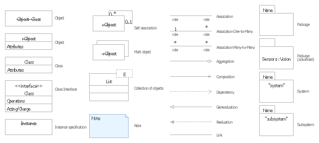
The vector stencils library "UML object diagrams" contains 26 symbols for the ConceptDraw PRO diagramming and vector drawing software.
"Each object and link on an object diagram is represented by an InstanceSpecification. This can show an object's classifier (e.g. an abstract or concrete class) and instance name, as well as attributes and other structural features using slots. Each slot corresponds to a single attribute or feature, and may include a value for that entity.
The name on an instance specification optionally shows an instance name, a ':' separator, and optionally one or more classifier names separated by commas. The contents of slots, if any, are included below the names, in a separate attribute compartment. A link is shown as a solid line, and represents an instance of an association. ...
If you are using a UML modeling tool, you will typically draw object diagrams using some other diagram type, such as on a class diagram. An object instance may be called an instance specification or just an instance. A link between instances is generally referred to as a link. Other UML entities, such as an aggregation or composition symbol (a diamond) may also appear on an object diagram." [Object diagram. Wikipedia]
The example "Design elements - UML object diagrams" is included in the Rapid UML solution from the Software Development area of ConceptDraw Solution Park.
UML object diagram symbols
- Association Symbols
- Symbol Of Association Aggregation And Composition Uml Example
- Entity Relationship Diagram Symbols | Labelled Figure Of ...
- Symbol Of Object Diagram
- Basic Flowchart Symbols and Meaning | Booch OOD Diagram ...
- DFD Flowchart Symbols | Booch OOD Diagram | UML Flowchart ...
- Soccer Pitch Symbols
- UML Flowchart Symbols | Memory Object Diagram | Design ...
- UML Flowchart Symbols | Memory Object Diagram | UML Sequence ...
- Self Association
- Symbols Of State Transition Diagram
- DFD Flowchart Symbols | Example of DFD for Online Store (Data ...
- Basic Flowchart Symbols and Meaning | Sample Project Flowchart ...
- Uml Class Symbols
- Booch OOD Diagram | Flow Chart Symbols | Gantt Chart In Ooad
- Symbols For Aggregation Inheritance And Association
- Biology Drawing Software | Organic Chemistry Symbols | Design ...
- Booch OOD Diagram | Primary Symbols Of Dfd
- Project Management Association
- Basic Flowchart Symbols and Meaning | Program Evaluation and ...
- ERD | Entity Relationship Diagrams, ERD Software for Mac and Win
- Flowchart | Basic Flowchart Symbols and Meaning
- Flowchart | Flowchart Design - Symbols, Shapes, Stencils and Icons
- Flowchart | Flow Chart Symbols
- Electrical | Electrical Drawing - Wiring and Circuits Schematics
- Flowchart | Common Flowchart Symbols
- Flowchart | Common Flowchart Symbols