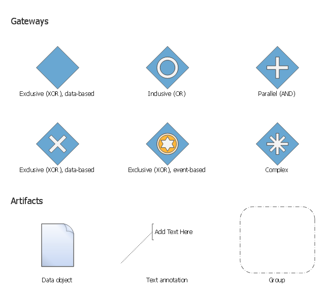
The vector stencils library "Gateways BPMN 1.2" contains symbols: data-based and event-based exclusive (XOR), inclusive (OR), parallel (AND), complex.
The vector stencils library "Artifacts BPMN 1.2" contains symbols: data object, text annotation, and group.
Use these shapes for creating the business process diagrams using the ConceptDraw PRO diagramming and vector drawing software.
"Gateway.
A gateway is represented with a diamond shape and determines forking and merging of paths, depending on the conditions expressed.
Exclusive.
Used to create alternative flows in a process because only one of the paths can be taken, it is called exclusive.
Event Based.
The condition determining the path of a process is based on an evaluated event.
Parallel.
Used to create parallel paths without evaluating any conditions.
Inclusive.
Used to create alternative flows where all paths are evaluated.
Exclusive Event Based.
An event is being evaluated to determine which of mutually exclusive paths will be taken.
Complex.
Used to model complex synchronization behavior.
Parallel Event Based.
Two parallel process are started based on an event but there is no evaluation of the event. ...
Artifacts allow developers to bring some more information into the model/ diagram. In this way the model/ diagram becomes more readable. There are three pre-defined Artifacts and they are:
(1) Data objects: Data objects show the reader which data is required or produced in an activity.
(2) Group: A Group is represented with a rounded-corner rectangle and dashed lines. The group is used to group different activities but does not affect the flow in the diagram.
(3) Annotation: An annotation is used to give the reader of the model/ diagram an understandable impression." [Business Process Model and Notation. Wikipedia]
The example "Design elements - Gateways and artifacts BPMN 1.2" is included in the Business Process Diagram solution from the Business Processes area of ConceptDraw Solution Park.
BPMN 1.2 gateway and artifact symbols
The vector stencils library "AWS Security, Identity and Compliance" contains 23 Amazon Web Services icons: AWS Directory Service, AWS Config, AWS CloudTrail, AWS Trusted Advisor, Amazon CloudWatch, Alarm. Use it to draw AWS architecture diagrams of your cloud infrastructure services.
"The AWS infrastructure puts strong safeguards in place to help protect customer privacy. All data is stored in highly secure AWS data centers. ...
AWS manages dozens of compliance programs in its infrastructure. This means that segments of your compliance have already been completed. ...
Cut costs by using AWS data centers. Maintain the highest standard of security without having to manage your own facility. ...
Security scales with your AWS cloud usage. No matter the size of your business the AWS infrastructure is designed to keep data safe." [aws.amazon.com/ security/ ]
The symbols example "AWS Security, Identity and Compliance - Vector stencils library" was created using the ConceptDraw PRO diagramming and vector drawing software extended with the AWS Architecture Diagrams solution from the Computer and Networks area of ConceptDraw Solution Park.
Amazon Inspector

Agent

AWS Artifact
AWS Certificate Manager

Certificate manager

AWS CloudHSM

AWS Directory Service

AWS IAM

Add-on
AWS STS
AWS STS (alternate)
-aws-security,-identity-and-compliance---vector-stencils-library.png--diagram-flowchart-example.png)
Data encryption key

Encrypted data
Long-term security credential

MFA token
Permissions
Role
Temporary security credential

AWS KMS
AWS Organizations

AWS Shield

AWS WAF

Filtering rule

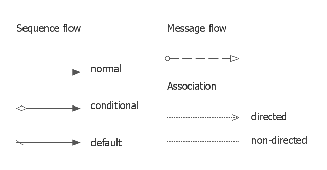
The vector stencils library "Connections BPMN1.2" contains 6 connection symbols of sequence flow, message flow, and association.
Use these shapes for drawing business process diagrams (BPMN 1.2) using the ConceptDraw PRO diagramming and vector drawing software.
"Connections.
Flow objects are connected to each other using Connecting objects, which are of three types: sequences, messages, and associations.
(1) Sequence Flow.
A Sequence Flow is represented with a solid line and arrowhead, and shows in which order the activities are performed. The sequence flow may also have a symbol at its start, a small diamond indicates one of a number of conditional flows from an activity, while a diagonal slash indicates the default flow from a decision or activity with conditional flows.
(2) Message Flow.
A Message Flow is represented with a dashed line, an open circle at the start, and an open arrowhead at the end. It tells us what messages flow across organizational boundaries (i.e., between pools). A message flow can never be used to connect activities or events within the same pool.
(3) Association.
An Association is represented with a dotted line. It is used to associate an Artifact or text to a Flow Object, and can indicate some directionality using an open arrowhead (toward the artifact to represent a result, from the artifact to represent an input, and both to indicate it is read and updated). No directionality is used when the Artifact or text is associated with a sequence or message flow (as that flow already shows the direction)." [Business Process Model and Notation. Wikipedia]
The example "Design elements - Connections BPMN1.2" is included in the Business Process Diagram solution from the Business Processes area of ConceptDraw Solution Park.
BPMN1.2 connection symbols
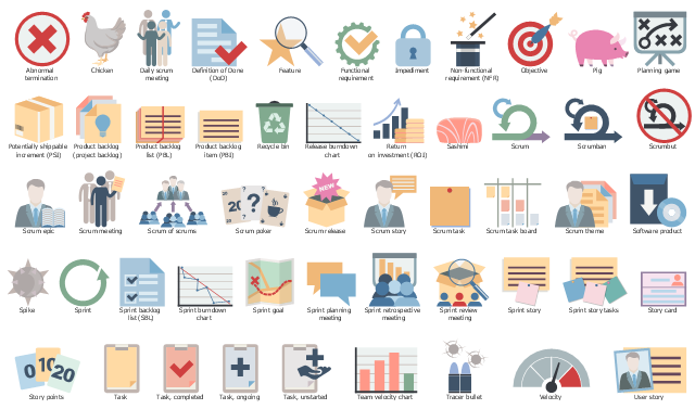
The vector stencils library "Scrum artifacts" contains 52 icons.
Use this clipart set to design your agile software development diagrams and infographics with ConceptDraw PRO software.
"Product backlog
The product backlog comprises an ordered list of requirements that a scrum team maintains for a product. It consists of features, bug fixes, non-functional requirements, etc.—whatever must be done to successfully deliver a viable product. The product owner orders the product backlog items (PBIs) based on considerations such as risk, business value, dependencies, and date needed. ...
Sprint backlog
The sprint backlog is the list of work the development team must address during the next sprint. The list is derived by the scrum team selecting product backlog items from the top of the product backlog until the development team feels it has enough work to fill the sprint. This is done by the development team asking "Can we also do this?" and adding product backlog items to the sprint backlog. The development team should keep in mind its past performance assessing its capacity for the new sprint, and use this as a guide line of how much "effort" they can complete.
The product backlog items may be broken down into tasks by the development team. Tasks on the sprint backlog are never assigned; rather, tasks are signed up for by the team members as needed according to the set priority and the development team member skills. This promotes self-organization of the development team, and developer buy-in. ...
Sprint burn-down chart
The sprint burndown chart is a public displayed chart showing remaining work in the sprint backlog. Updated every day, it gives a simple view of the sprint progress. ...
Release burn-down chart
The release burndown chart is the way for the team to track progress and provide visibility. The release burndown chart is updated at the end of each sprint by the scrum master. The horizontal axis of the release burndown chart shows the sprints; the vertical axis shows the amount of work remaining at the start of each sprint." [Scrum (software development). Wikipedia]
The clip art sample "Design elements - Scrum artifacts" is included in the Scrum solution from the Project Management area of ConceptDraw Solution Park.
Clipart set
"A deployment diagram in the Unified Modeling Language models the physical deployment of artifacts on nodes. To describe a web site, for example, a deployment diagram would show what hardware components ("nodes") exist (e.g., a web server, an application server, and a database server), what software components ("artifacts") run on each node (e.g., web application, database), and how the different pieces are connected (e.g. JDBC, REST, RMI)." [Deployment diagram. Wikipedia]
This UML deployment diagram example was created using the ConceptDraw PRO diagramming and vector drawing software extended with the Rapid UML solution from the Software Development area of ConceptDraw Solution Park.
This UML deployment diagram example was created using the ConceptDraw PRO diagramming and vector drawing software extended with the Rapid UML solution from the Software Development area of ConceptDraw Solution Park.
UML deployment diagram

The vector stencils library "AWS Security, Identity and Compliance" contains 23 Amazon Web Services icons: AWS Directory Service, AWS Config, AWS CloudTrail, AWS Trusted Advisor, Amazon CloudWatch, Alarm. Use it to draw AWS architecture diagrams of your cloud infrastructure services.
"The AWS infrastructure puts strong safeguards in place to help protect customer privacy. All data is stored in highly secure AWS data centers. ...
AWS manages dozens of compliance programs in its infrastructure. This means that segments of your compliance have already been completed. ...
Cut costs by using AWS data centers. Maintain the highest standard of security without having to manage your own facility. ...
Security scales with your AWS cloud usage. No matter the size of your business the AWS infrastructure is designed to keep data safe." [aws.amazon.com/ security/ ]
The symbols example "AWS Security, Identity and Compliance - Vector stencils library" was created using the ConceptDraw PRO diagramming and vector drawing software extended with the AWS Architecture Diagrams solution from the Computer and Networks area of ConceptDraw Solution Park.
"The AWS infrastructure puts strong safeguards in place to help protect customer privacy. All data is stored in highly secure AWS data centers. ...
AWS manages dozens of compliance programs in its infrastructure. This means that segments of your compliance have already been completed. ...
Cut costs by using AWS data centers. Maintain the highest standard of security without having to manage your own facility. ...
Security scales with your AWS cloud usage. No matter the size of your business the AWS infrastructure is designed to keep data safe." [aws.amazon.com/ security/ ]
The symbols example "AWS Security, Identity and Compliance - Vector stencils library" was created using the ConceptDraw PRO diagramming and vector drawing software extended with the AWS Architecture Diagrams solution from the Computer and Networks area of ConceptDraw Solution Park.
Amazon Inspector
Agent
AWS Artifact
AWS Certificate Manager
Certificate manager
AWS CloudHSM
AWS Directory Service
AWS IAM
Add-on
AWS STS
AWS STS (alternate)
Data encryption key
Encrypted data
Long-term security credential
MFA token
Permissions
Role
Temporary security credential
AWS KMS
AWS Organizations
AWS Shield
AWS WAF
Filtering rule
The vector stencils library "Bank UML deployment diagram" contains 10 shapes for drawing UML deployment diagrams.
Use it for object-oriented modeling of your bank information system.
"A deployment diagram in the Unified Modeling Language models the physical deployment of artifacts on nodes. To describe a web site, for example, a deployment diagram would show what hardware components ("nodes") exist (e.g., a web server, an application server, and a database server), what software components ("artifacts") run on each node (e.g., web application, database), and how the different pieces are connected (e.g. JDBC, REST, RMI).
The nodes appear as boxes, and the artifacts allocated to each node appear as rectangles within the boxes. Nodes may have subnodes, which appear as nested boxes. A single node in a deployment diagram may conceptually represent multiple physical nodes, such as a cluster of database servers.
There are two types of Nodes:
1. Device Node.
2. Execution Environment Node.
Device nodes are physical computing resources with processing memory and services to execute software, such as typical computers or mobile phones. An execution environment node (EEN) is a software computing resource that runs within an outer node and which itself provides a service to host and execute other executable software elements." [Deployment diagram. Wikipedia]
This example of UML deployment diagram symbols for the ConceptDraw PRO diagramming and vector drawing software is included in the ATM UML Diagrams solution from the Software Development area of ConceptDraw Solution Park.
UML deployment diagram symbols

"Deployment diagram shows execution architecture of systems that represent the assignment (deployment) of software artifacts to deployment targets (usually nodes).
Nodes represent either hardware devices or software execution environments. They could be connected through communication paths to create network systems of arbitrary complexity. Artifacts represent concrete elements in the physical world that are the result of a development process and are deployed on nodes.
Note, that components were directly deployed to nodes in UML 1.x deployment diagrams. In UML 2.x artifacts are deployed to nodes, and artifacts could manifest (implement) components. So components are now deployed to nodes indirectly through artifacts." [uml-diagrams.org/ deployment-diagrams.html]
The template "UML deployment diagram" for the ConceptDraw PRO diagramming and vector drawing software is included in the Rapid UML solution from the Software Development area of ConceptDraw Solution Park.
www.conceptdraw.com/ solution-park/ software-uml
UML deployment diagram

- Design elements - Gateways and artifacts BPMN 1.2 | Artifacts ...
- Design elements - Gateways and artifacts BPMN 1.2 | Design ...
- Design elements - Gateways and artifacts BPMN 1.2 | AWS Security ...
- Scrum | Draw Two Diagram Of A Artifact In The Market
- Design elements - Gateways and artifacts BPMN 1.2
- Scrum workflow | Design elements - Scrum artifacts | Scrum | Which ...
- Artifact Diagram For Atm Machine
- AWS Artifact
- Design elements - Gateways and artifacts BPMN 1.2 | Gateways ...
- Design elements - Gateways and artifacts BPMN 1.2 | BPMN 2.0 ...
- ERD | Entity Relationship Diagrams, ERD Software for Mac and Win
- Flowchart | Basic Flowchart Symbols and Meaning
- Flowchart | Flowchart Design - Symbols, Shapes, Stencils and Icons
- Flowchart | Flow Chart Symbols
- Electrical | Electrical Drawing - Wiring and Circuits Schematics
- Flowchart | Common Flowchart Symbols
- Flowchart | Common Flowchart Symbols