"The client–server model of computing is a distributed application structure that partitions tasks or workloads between the providers of a resource or service, called servers, and service requesters, called clients. Often clients and servers communicate over a computer network on separate hardware, but both client and server may reside in the same system. A server host runs one or more server programs which share their resources with clients. A client does not share any of its resources, but requests a server's content or service function. Clients therefore initiate communication sessions with servers which await incoming requests.
Examples of computer applications that use the client–server model are Email, network printing, and the World Wide Web." [Client–server model. Wikipedia]
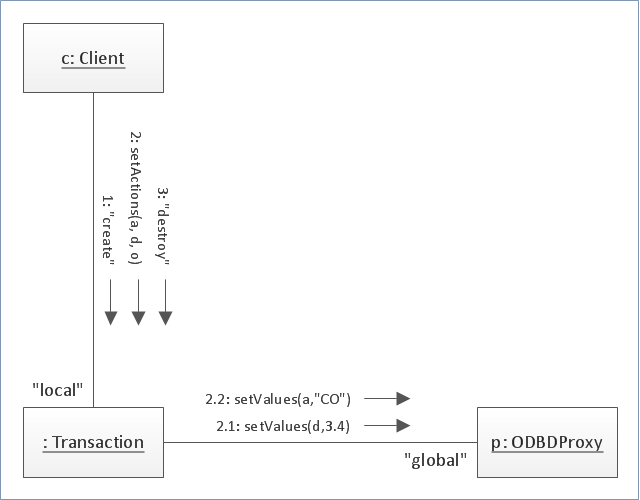
The UML communication diagram example "Client server access" was created using the ConceptDraw PRO diagramming and vector drawing software extended with the Rapid UML solution from the Software Development area of ConceptDraw Solution Park.
Examples of computer applications that use the client–server model are Email, network printing, and the World Wide Web." [Client–server model. Wikipedia]
The UML communication diagram example "Client server access" was created using the ConceptDraw PRO diagramming and vector drawing software extended with the Rapid UML solution from the Software Development area of ConceptDraw Solution Park.
UML communication diagram

 Business Process Diagrams
Business Process Diagrams solution extends the ConceptDraw PRO BPM software with RapidDraw interface, templates, samples and numerous libraries based on the BPMN 1.2 and BPMN 2.0 standards, which give you the possibility to visualize equally easy simple and complex processes, to design business models, to quickly develop and document in details any business processes on the stages of project’s planning and implementation.
"Communication diagram (called collaboration diagram in UML 1.x) is a kind of UML interaction diagram which shows interactions between objects and/ or parts (represented as lifelines) using sequenced messages in a free-form arrangement.
Communication diagram corresponds (i.e. could be converted to/ from or replaced by) to a simple sequence diagram without structuring mechanisms such as interaction uses and combined fragments. It is also assumed that message overtaking (i.e., the order of the receptions are different from the order of sending of a given set of messages) will not take place or is irrelevant." [uml-diagrams.org/ communication-diagrams.html]
The template "UML communication diagram" for the ConceptDraw PRO diagramming and vector drawing software is included in the Rapid UML solution from the Software Development area of ConceptDraw Solution Park.
www.conceptdraw.com/ solution-park/ software-uml
UML communication diagram
- UML communication diagram - Client server access | UML ...
- UML communication diagram - Client server access | Application ...
- Use Case Diagrams technology with ConceptDraw PRO ...
- Network diagrams with ConceptDraw PRO | UML communication ...
- UML Use Case Diagrams | Rapid UML | Communication Diagram ...
- UML Use Case Diagrams | UML communication diagram template ...
- UML communication diagram template | Diagramming Software for ...
- UML communication diagram - Client server access | Server rack ...
- Diagramming Software for Design UML Collaboration Diagrams ...
- Communication Diagram UML2.0 / Collaboration UML1.x ...
- Collaboration BPMN diagram - Application handling and invoicing ...
- Diagramming Software for Design UML Collaboration Diagrams ...
- Diagramming Software for Design UML Collaboration Diagrams ...
- Diagramming Software for Design UML Communication Diagrams ...
- Communication Diagram UML2.0 / Collaboration UML1.x | UML ...
- Communication Diagram UML2.0 / Collaboration UML1.x ...
- Diagramming Software for Design UML Communication Diagrams ...
- Mobile satellite communication network diagram ...
- UML Tool & UML Diagram Examples | UML communication diagram ...
- Communication Diagram UML2.0 / Collaboration UML1.x | UML ...
- ERD | Entity Relationship Diagrams, ERD Software for Mac and Win
- Flowchart | Basic Flowchart Symbols and Meaning
- Flowchart | Flowchart Design - Symbols, Shapes, Stencils and Icons
- Flowchart | Flow Chart Symbols
- Electrical | Electrical Drawing - Wiring and Circuits Schematics
- Flowchart | Common Flowchart Symbols
- Flowchart | Common Flowchart Symbols