Fault Tree Analysis Software

First of all, Fault Tree Analysis Diagrams Solution provides a set of samples which are the good examples of easy drawing professional looking Fault Tree Analysis Diagrams.
HelpDesk
How to Create a Fault Tree Analysis Diagram (FTD)

Swim Lane Flowchart Symbols

Circuits and Logic Diagram Software

Electrical Engineering solution helps you create quick and easy: Electrical schematics, Digital and analog logic designs, Circuit and wiring schematics and diagrams, Power systems diagrams, Maintenance and repair diagrams, Circuit board and amplifier diagrams, Integrated circuit schematics.
Total Quality Management Definition

Wiring Diagrams with ConceptDraw DIAGRAM

Process Flow Diagram

ConceptDraw DIAGRAM diagramming and vector drawing software extended with powerful tools of Flowcharts Solution from the "Diagrams" Area of ConceptDraw Solution Park is effective for drawing: Process Flow Diagram, Flow Process Diagram, Business Process Flow Diagrams.
Electrical Drawing Software and Electrical Symbols

Electrical Drawing Software provides the 26 stencils libraries of ready-to-use predesigned vector electrical symbols, templates and samples that make your electrical drawing quick, easy and effective.
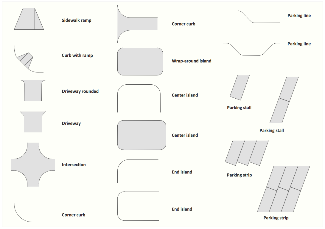
Interior Design. Site Plan — Design Elements
Once you try ConceptDraw DIAGRAM product, you will recommend it to lots of other people you know and you care for, such as your friends, acquaintances, colleagues and business partners as this application is truly incredible and useful in drawing so many things which can be helpful for your use.
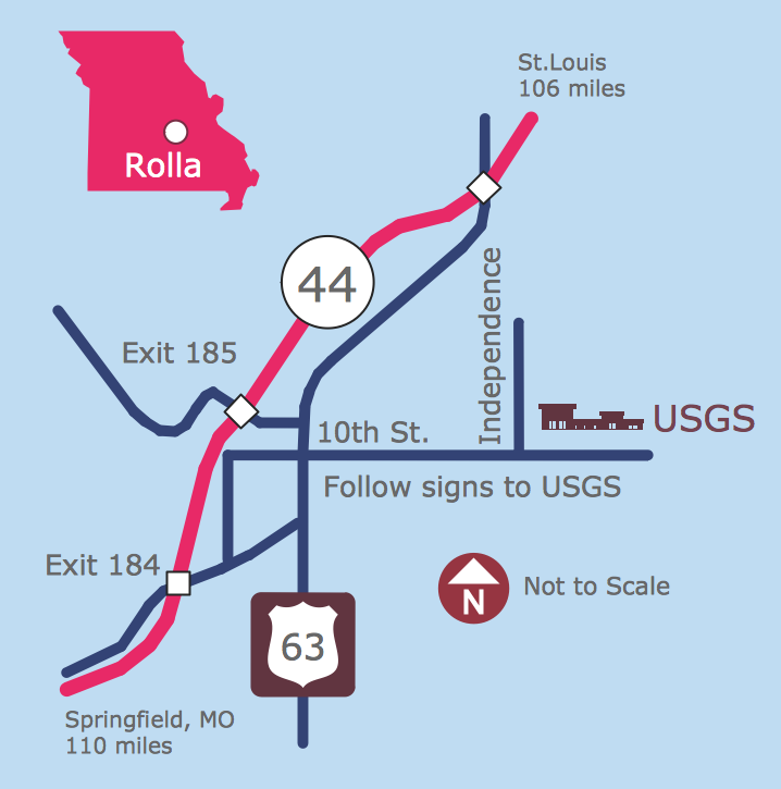
Maps and Directions
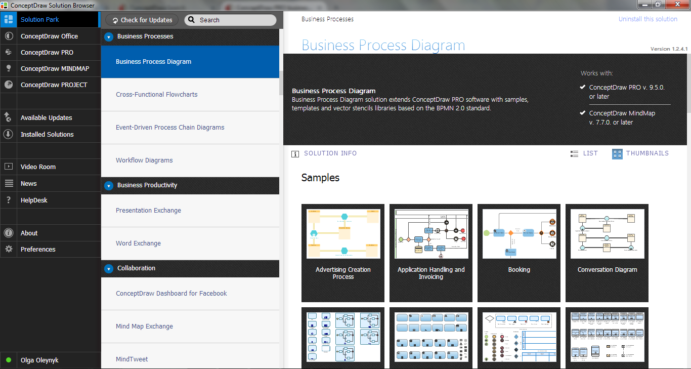
ConceptDraw DIAGRAM
Mechanical Design Software

Mechanical Drawing Software

HelpDesk
How to Develop a Business Process Model

 Electrical Engineering
This solution extends ConceptDraw DIAGRAM.9.5 (or later) with electrical engineering samples, electrical schematic symbols, electrical diagram symbols, templates and libraries of design elements, to help you design electrical schematics, digital and analog
- Engineering | Flowchart For Universal Gate
- Basic Flowchart Symbols and Meaning | Audit Flowchart Symbols ...
- Logic Gate Flowchart
- And Gate Flowchart
- Flowchart For And Gate
- Flowchart For Solving And Gate
- Flow Chart Gates
- Electrical Symbols — Logic Gate Diagram | Process Flowchart ...
- Flowchart Software | Design elements - Logic gate diagram | Speed ...
- Contoh Flowchart Di Area Gate
- Circuits and Logic Diagram Software | Samples of Flowchart ...
- Basic Flowchart Symbols and Meaning | Types of Flowcharts ...
- Basic Flowchart Symbols and Meaning | Process Flowchart | Audit ...
- Solving quadratic equation algorithm - Flowchart | Basic Flowchart ...
- Process Flowchart | Types of Flowchart - Overview | Control and ...
- Basic Flowchart Symbols and Meaning | HR arrows - Vector stencils ...
- Euclidean algorithm - Flowchart | Basic Flowchart Symbols and ...
- Basic Flowchart Symbols and Meaning | How to Create a ...
- Process Flowchart | Process Flow Diagram Symbols | Instruments ...
- Sales Process Flowchart . Flowchart Examples | Value stream with ...
- ERD | Entity Relationship Diagrams, ERD Software for Mac and Win
- Flowchart | Basic Flowchart Symbols and Meaning
- Flowchart | Flowchart Design - Symbols, Shapes, Stencils and Icons
- Flowchart | Flow Chart Symbols
- Electrical | Electrical Drawing - Wiring and Circuits Schematics
- Flowchart | Common Flowchart Symbols
- Flowchart | Common Flowchart Symbols