 ATM UML Diagrams
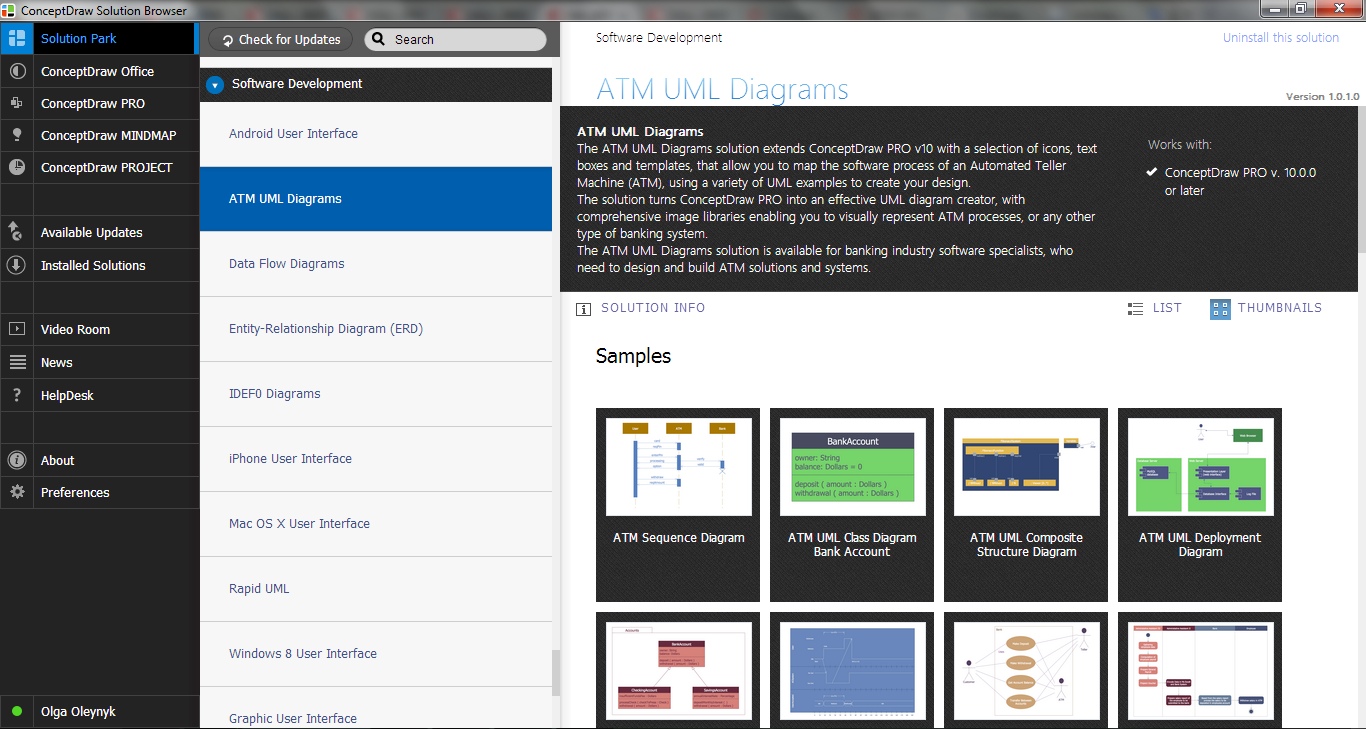
The ATM UML Diagrams solution lets you create ATM solutions and UML examples. Use ConceptDraw DIAGRAM as a UML diagram creator to visualize a banking system.
UML Use Case Diagram Example. Services UML Diagram. ATM system

This sample shows the scheme of the servicing using the ATMs (Automated Teller Machines) and is used at the working of ATM banking systems, at the performing of the banking transactions.
HelpDesk
How to Create a Bank ATM Use Case Diagram

ConceptDraw DIAGRAM diagramming software, enhanced and expanded with the ATM UML Diagrams solution, offers the full range of icons, templates and design elements needed to faithfully represent ATM and banking information system architecture using UML standards. The ATM UML Diagrams solution is useful for beginner and advanced users alike. More experienced users will appreciate a full range of vector stencil libraries and ConceptDraw DIAGRAM's powerful software, that allows you to create your ATM UML diagram in a matter of moments.
UML Diagram

Create unified modeling language (UML) diagrams with ConceptDraw.
Yourdon and Coad Diagram

Model Based Systems Engineering

Account Flowchart Stockbridge System. Flowchart Examples

This is a flowchart of a data processing system combining manual and computerized processing to handle accounts receivable, billing, and general ledger.
UML Business Process

Design Elements for UML Diagrams

Timing diagram


ATM Solutions
UML Deployment Diagram. Design Elements

ConceptDraw has 393 vector stencils in the 13 libraries that helps you to start using software for designing your own UML Diagrams. You can use the appropriate stencils of UML notation from UML Deployment library.
 Rapid UML
Rapid UML solution extends ConceptDraw DIAGRAM software with templates, samples and libraries of vector stencils for quick drawing the UML diagrams using Rapid Draw technology.
The vector stencils library "Bank UML package diagram" contains 5 shapes for drawing UML package diagrams.
Use it for object-oriented modeling of your bank information system.
"A package diagram in the Unified Modeling Language depicts the dependencies between the packages that make up a model.
In addition to the standard UML Dependency relationship, there are two special types of dependencies defined between packages:
* package import,
* package merge.
Elements.
1. Package: a general purpose mechanism for organizing model elements & diagrams into groups. It provides an encapsulated namespace within which all the names must be unique. It is used to group semantically related elements. It is a namespace as well as an element that can be contained in other packages' namespaces.
2. Class: a representation of an object that reflects its structure and behavior within the system. It is a template from which running instances are created. Classes usually describe the logical structure of the system.
3. Interface: a specification of behavior. An implementation class must be written to support the behavior of an interface class.
4. Object: an instance of a class. It is often used in analysis to represent an artifact or other item.
5. Table: a stereotyped class." [Package diagram. Wikipedia]
This example of UML package diagram symbols for the ConceptDraw PRO diagramming and vector drawing software is included in the ATM UML Diagrams solution from the Software Development area of ConceptDraw Solution Park.
UML package diagram symbols

UML Class Diagram Example - Apartment Plan

This sample show the detailed plan of the apartment and is used by building companies, design apartments, real estate agencies, at the buying / selling of the realty.
- PM Easy | Banking System | Quality Mind Map | Mindmap Diagrams ...
- Rapid UML | Slip System Of Banking Diagrams To Analysis
- Analysis Model For A Banking System
- UML Diagram | Fishbone Diagram | Banking System | Class ...
- Data Structures Diagram For Bank System
- UML Diagram | SWOT Analysis | Calendars | Class Diagram In Uml ...
- Process Flowchart | UML Diagram | Data Flow Diagram | Diagrams ...
- Credit Card Processing System UML Diagram | Bank System | UML ...
- UML use case diagram - Banking system
- External Entity For Banking System In System Analysis And Design
- UML for Bank | UML use case diagram - Banking system | Bank UML ...
- Credit Card Processing System UML Diagram | Bank System | UML ...
- Bank System | UML Collaboration Diagram Example Illustration ...
- Credit Card Processing System UML Diagram | Structured Systems ...
- Credit Card Processing System UML Diagram | Bank System | UML ...
- Credit Card Processing System UML Diagram | Bank System | Entity ...
- UML Diagram | Process Flowchart | Structured Systems Analysis ...
- Online Banking System Block Diagram
- System Flow Chart For Online Banking System
- UML use case diagram - Banking system | UML Use Case Diagram ...
- ERD | Entity Relationship Diagrams, ERD Software for Mac and Win
- Flowchart | Basic Flowchart Symbols and Meaning
- Flowchart | Flowchart Design - Symbols, Shapes, Stencils and Icons
- Flowchart | Flow Chart Symbols
- Electrical | Electrical Drawing - Wiring and Circuits Schematics
- Flowchart | Common Flowchart Symbols
- Flowchart | Common Flowchart Symbols