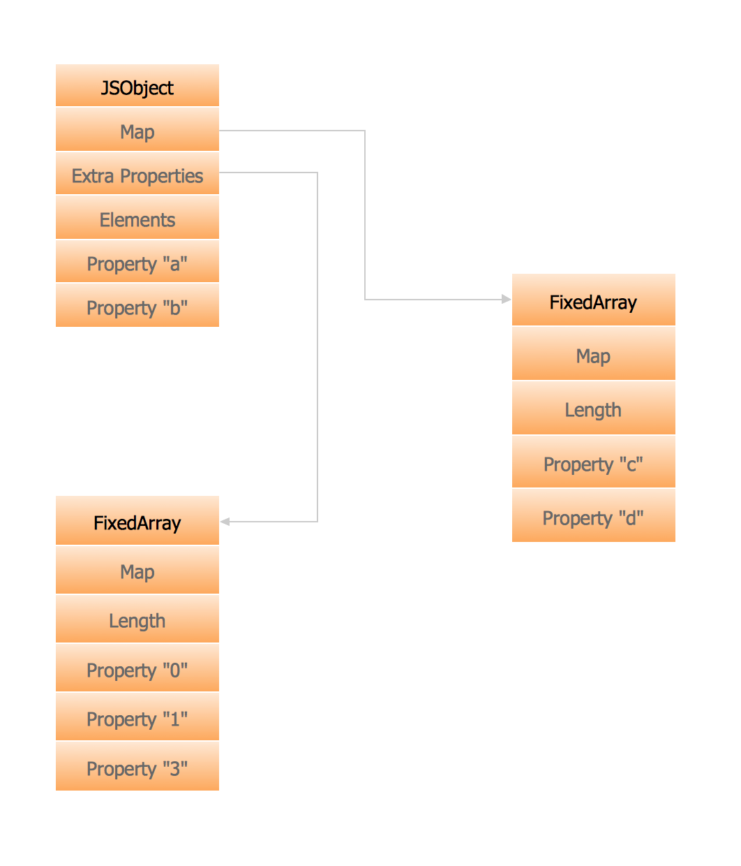
Memory Object Diagram
UML Object Diagram. Design Elements

ConceptDraw has 393 vector stencils in the 13 libraries that helps you to start using software for designing your own UML Diagrams. You can use the appropriate stencils of UML notation from UML Object library.
Diagramming Software for Design UML Object Diagrams

ConceptDraw Rapid UML solution delivers libraries contain pre-designed objects fit UML notation, and ready to draw professional UML Object Diagram.

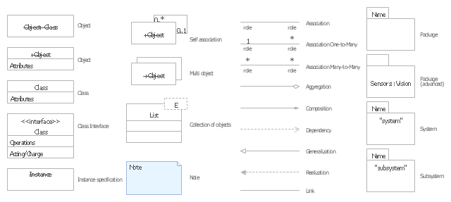
The vector stencils library "UML object diagrams" contains 26 symbols for the ConceptDraw PRO diagramming and vector drawing software.
"Each object and link on an object diagram is represented by an InstanceSpecification. This can show an object's classifier (e.g. an abstract or concrete class) and instance name, as well as attributes and other structural features using slots. Each slot corresponds to a single attribute or feature, and may include a value for that entity.
The name on an instance specification optionally shows an instance name, a ':' separator, and optionally one or more classifier names separated by commas. The contents of slots, if any, are included below the names, in a separate attribute compartment. A link is shown as a solid line, and represents an instance of an association. ...
If you are using a UML modeling tool, you will typically draw object diagrams using some other diagram type, such as on a class diagram. An object instance may be called an instance specification or just an instance. A link between instances is generally referred to as a link. Other UML entities, such as an aggregation or composition symbol (a diamond) may also appear on an object diagram." [Object diagram. Wikipedia]
The example "Design elements - UML object diagrams" is included in the Rapid UML solution from the Software Development area of ConceptDraw Solution Park.
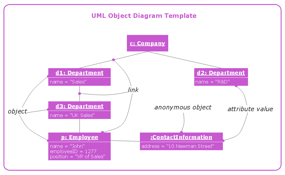
UML object diagram symbols
UML Diagram

Create unified modeling language (UML) diagrams with ConceptDraw.
Booch OOD Diagram

OMT Method

All diagrams produced with ConceptDraw DIAGRAM are vector graphic documents and are available for reviewing, modifying, and converting to a variety of formats (image, HTML, PDF file, MS PowerPoint Presentation, Adobe Flash or MS Visio XML).
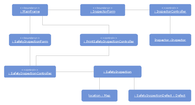
"In software engineering, software system safety optimizes system safety in the design, development, use, and maintenance of software systems and their integration with safety-critical hardware systems in an operational environment." [Software system safety. Wikipedia]
The UML object diagram example "Safety inspection" was created using the ConceptDraw PRO diagramming and vector drawing software extended with the Rapid UML solution from the Software Development area of ConceptDraw Solution Park.
The UML object diagram example "Safety inspection" was created using the ConceptDraw PRO diagramming and vector drawing software extended with the Rapid UML solution from the Software Development area of ConceptDraw Solution Park.
UML object diagram
 ATM UML Diagrams
The ATM UML Diagrams solution lets you create ATM solutions and UML examples. Use ConceptDraw DIAGRAM as a UML diagram creator to visualize a banking system.
HelpDesk
How to Create a Bank ATM Use Case Diagram

ConceptDraw DIAGRAM diagramming software, enhanced and expanded with the ATM UML Diagrams solution, offers the full range of icons, templates and design elements needed to faithfully represent ATM and banking information system architecture using UML standards. The ATM UML Diagrams solution is useful for beginner and advanced users alike. More experienced users will appreciate a full range of vector stencil libraries and ConceptDraw DIAGRAM's powerful software, that allows you to create your ATM UML diagram in a matter of moments.
UML Diagram Types List

UML Component Diagram Example - Online Shopping

This sample shows the concept of the online shopping and is used for the understanding of the online shopping processes, of the online shops working processes, for projection and creating of the online stores.
Diagramming Software for Design UML Activity Diagrams

ORM Diagram

- Memory Object Diagram | UML Sequence Diagram. Design ...
- Memory Object Diagram | UML Object Diagram . Design Elements ...
- Diagramming Software for Design UML Object Diagrams ...
- UML Object Diagram . Design Elements | Business Process ...
- UML Flowchart Symbols | Memory Object Diagram | UML Sequence ...
- UML Flowchart Symbols | Memory Object Diagram | Design ...
- UML Object Diagram . Design Elements | Diagramming Software for ...
- UML Object Diagram . Design Elements | UML Deployment Diagram ...
- UML Object Diagram . Design Elements | UML Collaboration ...
- Diagramming Software for Design UML Object Diagrams | UML ...
- Draw Object Diagram For Bank Information System
- Entity Relationship Diagram Symbols | Design elements - Bank UML ...
- Object Diagram Bank Atm Uml
- Design elements - Solid geometry | Design elements - UML object ...
- Design elements - UML class diagrams | UML Object Diagram ...
- Object Uml Diagram
- Workflow Diagram Software Mac | UML Sequence Diagram . Design ...
- Line Chart Examples | Memory Object Diagram | Geo Map - Africa ...
- UML Class Diagram Notation
- Sample Object Diagram For Library Management System
- ERD | Entity Relationship Diagrams, ERD Software for Mac and Win
- Flowchart | Basic Flowchart Symbols and Meaning
- Flowchart | Flowchart Design - Symbols, Shapes, Stencils and Icons
- Flowchart | Flow Chart Symbols
- Electrical | Electrical Drawing - Wiring and Circuits Schematics
- Flowchart | Common Flowchart Symbols
- Flowchart | Common Flowchart Symbols