COM and OLE Diagram

Booch OOD Diagram

Examples for OOSE Method

UML Class Diagram Notation

UML Class Diagram. Design Elements

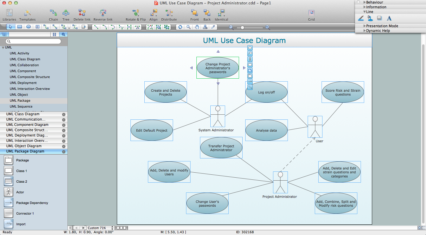
UML for Software Engineers
UML Composite Structure Diagram. Design Elements

ConceptDraw has 393 vector stencils in the 13 libraries that helps you to start using software for designing your own UML Diagrams. You can use the appropriate stencils of UML notation from UML Composite Structure library.
Object-Oriented Development (OOD) Method

This sample was created in ConceptDraw DIAGRAM diagramming and vector drawing software using the Rapid UML Solution from the Software Development area of ConceptDraw Solution Park.
UML Class Diagram Constructor

The Rapid UML Solution for ConceptDraw DIAGRAM includes the UML Class Diagram library that helps you to design the UML Class Diagram quick and easy. You can simply and quickly drop the ready-to-use objects from the library into your document to create the UML Class Diagram.
UML Notation

Two types of diagrams are used in UML: Structure Diagrams and Behavior Diagrams. Behavior Diagrams represent the processes proceeding in a modeled environment. Structure Diagrams represent the elements that compose the system.
UML Component Diagram. Design Elements

Rapid UML Solution for ConceptDraw DIAGRAM contains 13 vector stencils libraries with 393 interactive shapes that you can use to design your UML diagrams.
To design a Component Diagram use the UML Component Diagram library.
UML Component Diagram library contains 36 shapes

UML Deployment Diagram. Design Elements

ConceptDraw has 393 vector stencils in the 13 libraries that helps you to start using software for designing your own UML Diagrams. You can use the appropriate stencils of UML notation from UML Deployment library.
Software Diagrams

ConceptDraw DIAGRAM is a perfect tool for Designing and planning tasks; Developing Visualization Solutions; Project Planning (Gantt Charts, Timelines, Project Schedules).
UML Business Process

- Booch OOD Diagram | OOSE Method | UML for Software Engineers ...
- Online Shopping With Aggregation Composition Generalization
- Aggregation And Association And Composition Library Management
- Booch OOD Diagram | UML for Software Engineers | OOSE Method ...
- Symbol Of Association Aggregation And Composition Uml Example
- Scheduling Using The Gantt Chart With The Construction Of The ...
- Object-Oriented Design | Booch OOD Diagram | Coad/Yourdon's ...
- Booch OOD Diagram | Software Diagrams | SSADM Diagram ...
- Entity Relationship Diagram Software Engineering | Booch OOD ...
- Gane Sarson Diagram | Data Flow Diagram Symbols. DFD Library ...
- Software Engineering Er Diagram Of Online Shopping Management
- Booch OOD Diagram | Entity Relationship Diagram Software ...
- Booch OOD Diagram | OOSE Method | Examples for OOSE Method ...
- Memory Object Diagram | Program Structure Diagram | Booch OOD ...
- Data Flow Diagram For Hospital In Software Engineering
- Jacabson Model In Software Engineering
- UML Diagram Types List | UML Class Diagram Generalization ...
- Booch OOD Diagram | Object-Oriented Development (OOD) Method ...
- Software Engineering Model Of Online Shopping
- Object-Oriented Design | IDEF | OOSE Method | Object Oriented ...
- ERD | Entity Relationship Diagrams, ERD Software for Mac and Win
- Flowchart | Basic Flowchart Symbols and Meaning
- Flowchart | Flowchart Design - Symbols, Shapes, Stencils and Icons
- Flowchart | Flow Chart Symbols
- Electrical | Electrical Drawing - Wiring and Circuits Schematics
- Flowchart | Common Flowchart Symbols
- Flowchart | Common Flowchart Symbols