UML Use Case Diagram Example. Social Networking Sites Project

This sample shows the Facebook Socio-health system and is used at the projection and creating of the social networking sites.
UML Activity Diagram

Use ConceptDraw DIAGRAM diagramming and vector drawing software enhanced with Rapid UML solution from ConceptDraw Solution Park to create your own UML activity diagrams that show the business and operational workflows of components and overall flow of control in your systems. Such software provides coloring UML diagrams for various purposes and simplifying work of the engineers.
Activity Network Diagram Method

This sample shows the PERT (Program Evaluation Review Technique) chart of the request on proposal. A request for proposal (RFP) is a request of the company or the organization to potential suppliers to submit the business proposals for service or goods that it is interested to purchase. The RFP is represented on the initial procurement stage and allows to define the risks and benefits.
Activity on Node Network Diagramming Tool

This sample shows the Activity on node network diagramming method. It was created in ConceptDraw DIAGRAM diagramming and vector drawing software using the Seven Management and Planning Tools solution from the Management area of ConceptDraw Solution Park.
UML Class Diagram Example - Social Networking Site
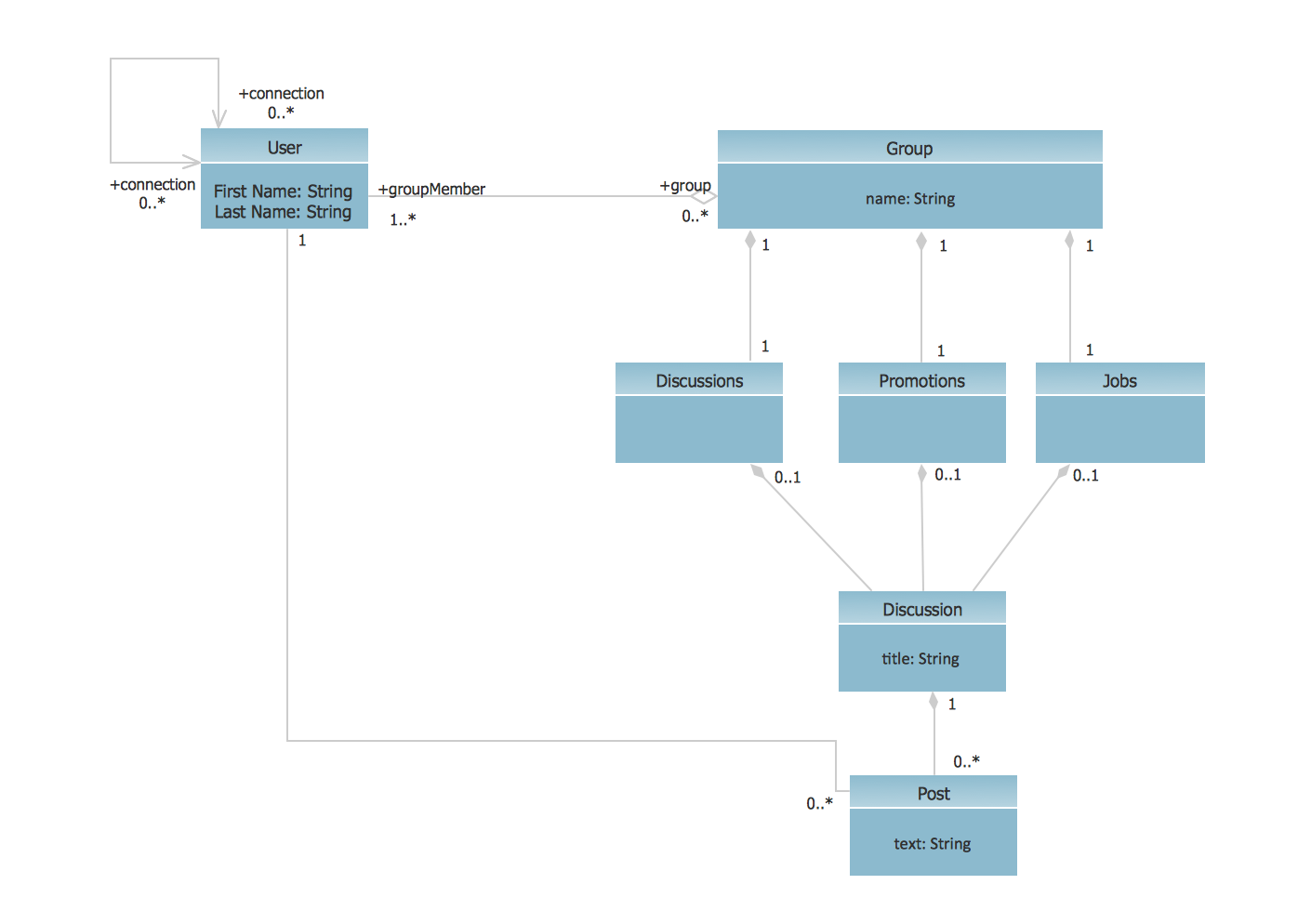
This sample shows the structure of the popular social networking site Linkedin and is used in the business field, in IT, at the projection and creating of the social networking sites.
UML Diagram for System

Swim Lane Flowchart Symbols

UML Sample Project

UML Use Case Diagram Example - Estate Agency

This sample shows the work of the estate agency and is used by the estate agencies, building companies, at the trainings of the estate agencies, for understanding the working processes of the estate agencies.
UML Deployment Diagram Example - ATM System UML diagrams

This sample shows the work of the ATM (Automated Teller Machine) banking system that is used for service and performing of the banking transactions using ATMs. System engineers can use comprehensive UML diagrams solution.
Activity Network (PERT) Chart

This diagram is constructed as part of the process in creating a schedule of corrective actions. The Activity Network Chart (PERT) shows the logical connections and consequence of tasks to be performed. It displays the time period for problem solving and the implementation of all activities through the critical path.
Diagramming Software for Design UML Use Case Diagrams


Draw Network Diagram based on Templates and Examples


Diagramming Software for Design UML Communication Diagrams

Entity-Relationship Diagram (ERD) with ConceptDraw DIAGRAM

one-to-many, many-to-many.
Draw Entity-Relationship Diagrams (ERD) easily with ConceptDraw extended with Entity-Relationship Diagram (ERD) Solution from the Software Development Area. Use ERD software to create ER diagram.

- Activity Diagram For Social Networking Site Project
- Activity Diagram For Social Networking Project
- UML Use Case Diagram Example Social Networking Sites Project ...
- Advertisement System Project Activity Diagram Download
- For Website Draw Activity Diagram
- UML Activity Diagram | Activity on Node Network Diagramming Tool ...
- UML Sample Project | UML Use Case Diagram Example Social ...
- Social Networking Site Activity Diagram
- UML Activity Diagram | UML Use Case Diagram Example Social ...
- Example Of Activity Diagram For Project Management System
- Activity Diagram For The Project Bug Tracking System
- Activity Diagram For The Website Access
- UML Activity Diagram | UML Diagram of Parking | UML Use Case ...
- Activity Diagram For Mobile Communication System
- Activity Diagram For Project Management System
- Activity Diagrams For Facebook
- UML Class Diagram Example - Social Networking Site | UML Use ...
- UML Class Diagram Generalization Example UML Diagrams | UML ...
- Activity Diagram Facebook
- Deployment Diagram Of Social Networking Site
- ERD | Entity Relationship Diagrams, ERD Software for Mac and Win
- Flowchart | Basic Flowchart Symbols and Meaning
- Flowchart | Flowchart Design - Symbols, Shapes, Stencils and Icons
- Flowchart | Flow Chart Symbols
- Electrical | Electrical Drawing - Wiring and Circuits Schematics
- Flowchart | Common Flowchart Symbols
- Flowchart | Common Flowchart Symbols