UML Class Diagram Example - Apartment Plan

This sample show the detailed plan of the apartment and is used by building companies, design apartments, real estate agencies, at the buying / selling of the realty.
UML Use Case Diagram Example. Registration System

This sample was created in ConceptDraw DIAGRAM diagramming and vector drawing software using the UML Use Case Diagram library of the Rapid UML Solution from the Software Development area of ConceptDraw Solution Park.
This sample shows the types of user’s interactions with the system and is used at the registration and working with the database system.
UML Package Diagram. Design Elements

ConceptDraw has 393 vector stencils in the 13 libraries that helps you to start using software for designing your own UML Diagrams. You can use the appropriate stencils of UML notation from UML Package library.
UML Class Diagram Notation

Diagramming Software for Design UML Activity Diagrams


Booch OOD Diagram

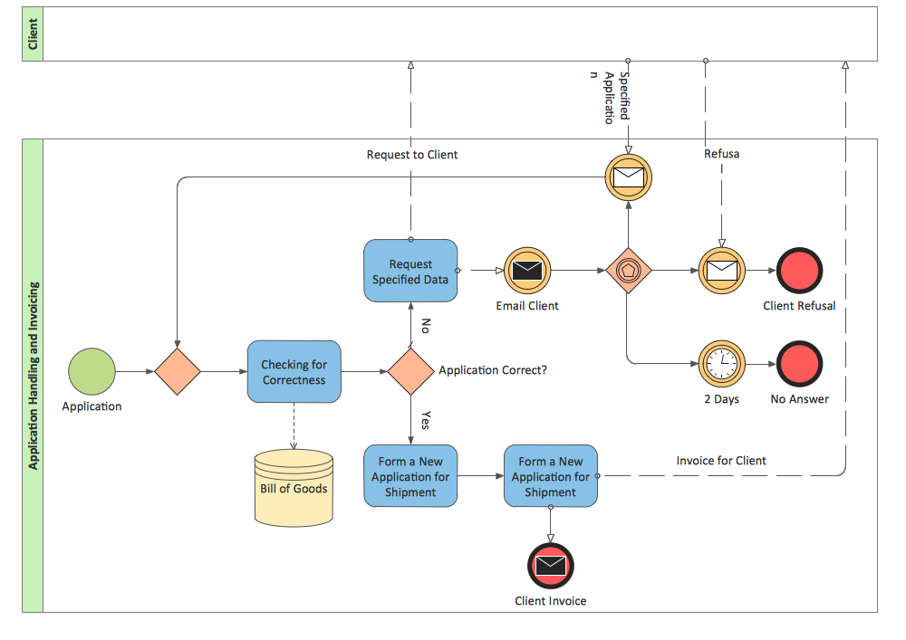
BPMN 2.0
UML Activity Diagram. Design Elements

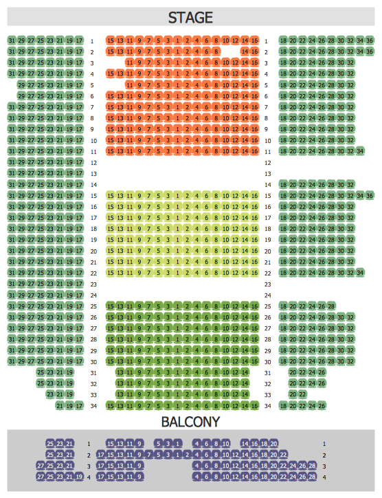
Seating Arrangement
Data Flow Diagram

- Example Activity Diagram Library Management System Pdf
- Activity Diagram For Library Management System Ppt
- Draw UML Activity Diagrams For Library Management System
- Create A Class Diagram For Library Management Using Classes ...
- ATM UML Diagrams | Oop Diagram On Library Management System
- Activity Diagram For Library Management System In Uml
- Use Case Diagram For Library Management System Pdf
- Class Diagram For Library Management System Ppt
- Rapid UML | Package Diagram For Library Management System Pdf
- Sample Object Diagram For Library Management System
- ERD | Entity Relationship Diagrams, ERD Software for Mac and Win
- Flowchart | Basic Flowchart Symbols and Meaning
- Flowchart | Flowchart Design - Symbols, Shapes, Stencils and Icons
- Flowchart | Flow Chart Symbols
- Electrical | Electrical Drawing - Wiring and Circuits Schematics
- Flowchart | Common Flowchart Symbols
- Flowchart | Common Flowchart Symbols